11 Expansion Unit
11 - 6
GX-series EtherCAT Slave Unit User’s Manual
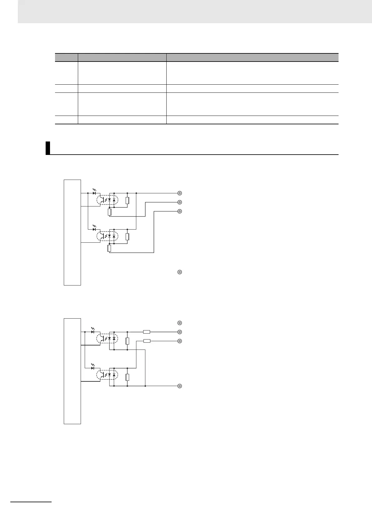
XWT-ID08 (NPN)
XWT-ID08-1 (PNP)
No. Name Function
(1) Input indicators (0 to 7)
Indicates the state of each input contact (ON/OFF).
Not lit: Contact OFF (input OFF state)
Lit in yellow: Contact ON (input ON state)
(2) Slave connector Connects the connector on the right side of the Slave Unit.
(3) Terminal block
Connects external devices and the I/O power supply.
V, G: I/O power supply terminals
0 to 7: Input terminals
(4) DIN track mounting hook Fixes a Slave Unit to a DIN track.
Internal circuits diagram
V 24 VDC
0
1
G
Photocoupler
Photocoupler
Internal circuits
•
•
•
•
•
•
•
•
•
•
•
•
•
•
•
•
•
•
•
•
•
V 24 VDC
0
1
G
Photocoupler
Photocoupler
•
•
•
•
•
•
•
•
•
•
•
•
•
•
Internal circuits
•
•
•

 Loading...