5-2
User Parameter Descriptions
This section describes the contents of the user parameter tables.
Description of User Parameter Tables
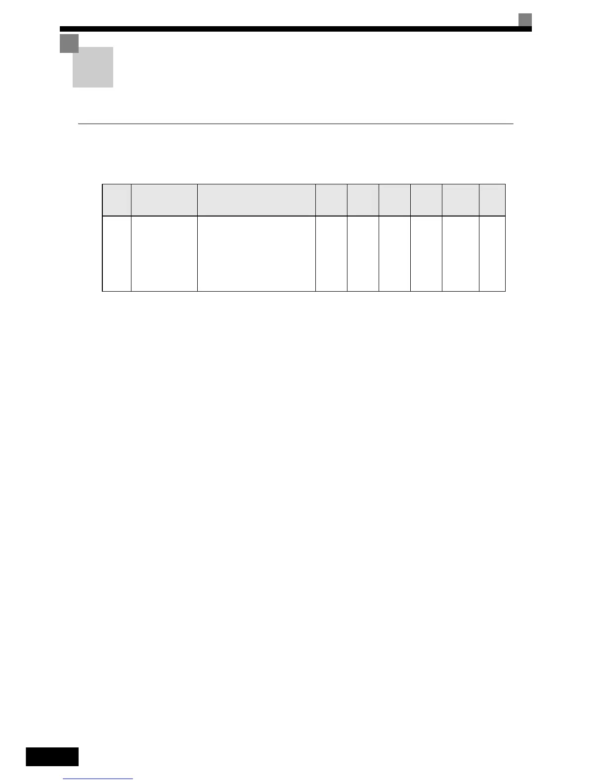
User parameter tables are structured as shown below. Here b1-01 (Frequency Reference Selection) is used as
an example.
Param-
eter
Number
Name Description
Setting
Range
Factory
Setting
Change
during
Opera-
tion
Access
Level
MEMO-
BUS Reg-
ister
Page
b1-01
Reference selec-
tion
Sets the frequency reference
input method.
0: Digital Operator
1: Control circuit terminal (ana-
log input)
2: MEMOBUS communications
3: Option Card
0 to 3 1 No Q 180H –
• Parameter Number: The number of the user parameter.
• Name: The name of the user parameter.
• Description: Details on the function or settings of the user parameter.
• Setting Range: The setting range for the user parameter.
• Factory Setting: The default setting of the user parameter.
• Change during Operation:
Indicates whether the parameter can be changed while the Inverter is
in operation or not.
Yes: Changes are possible during operation.
No: Changes are not possible during operation.
• Access Level:
Indicates the parameter access level in which the parameter can be
changed or monitored.
Q: Quick programming mode and advanced programming mode.
A: Advanced programming mode only.
• MEMOBUS Register: The register number used for MEMOBUS communications.
• Page: Reference page for more detailed information about the parameter.
 Loading...


