Installing and Wiring Option Cards
2-39
Installation in IP54 Inverters
Before mounting an Option Card, open the inverter door and be sure that the charge indicator inside the
Inverter does not glow anymore. After that remove the option clip and mount the Option Card like with the
IP00 or NEMA 1 Inverter.
Cable Gland Size for Option Cards
Refer to the terminal specification in each option card’s manual..
Wiring Method for Option Cards
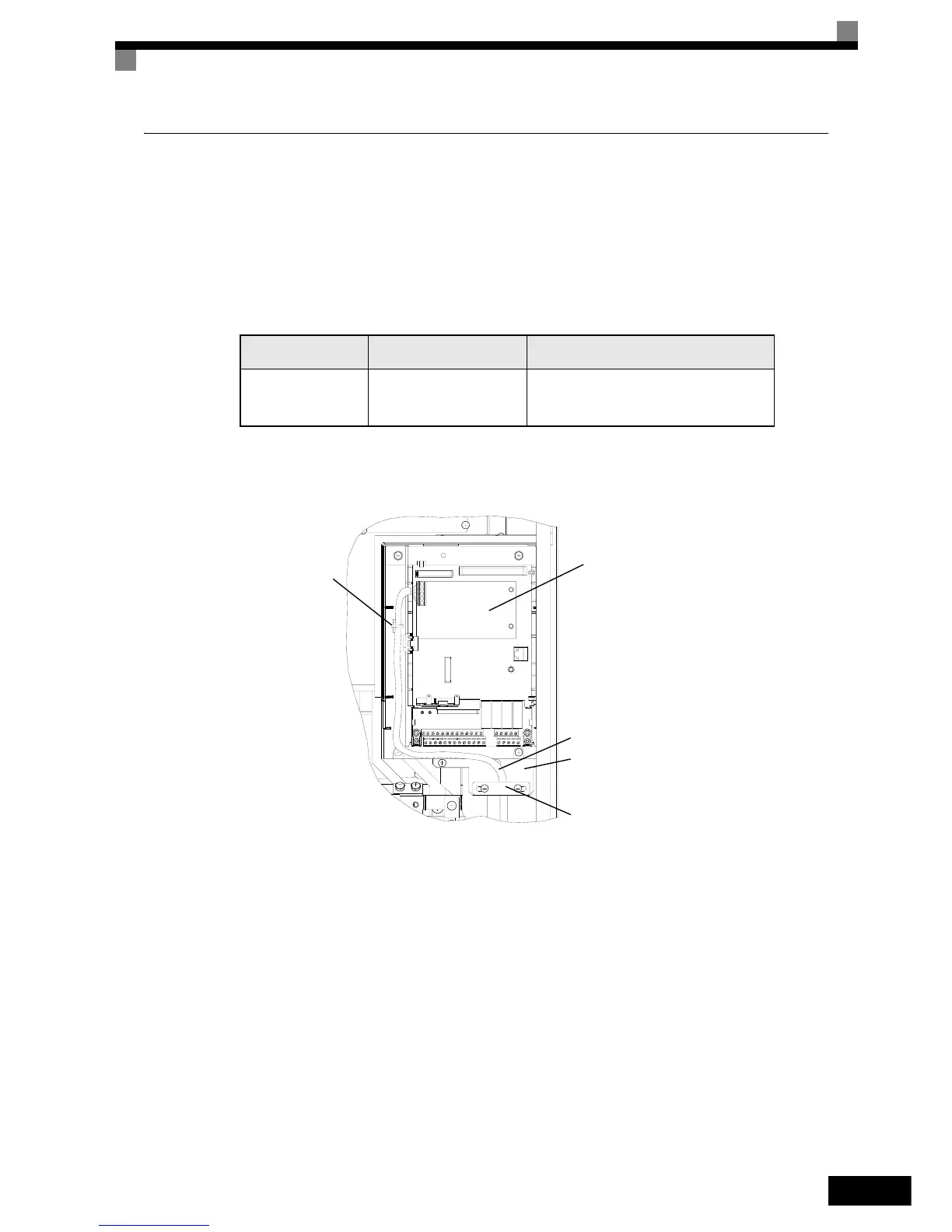
For the wiring refer to page 2-29 and to Fig 2.23 below.
Fig 2.23 Option Card Wiring for Inverters with 22 to 55kW
Table 2.17 Cable Gland Size for Option Cards
Cable Gland Size
Possible Clamping
Cable Diameter (mm)
Wire Type
M16
*1
*1. Refer to Table 2.5 for tightening torques for the cable glands.
4.5 to 7
• Shielded twisted-pair wire
• Shielded, PVC multi-core cable
(e.g. Lappkabel Ölflex)
Option Card
Option Cable
Cable Tie
(optional)
Cable Mounting Base
Earth Clamp
 Loading...


