3-8
Drive Mode
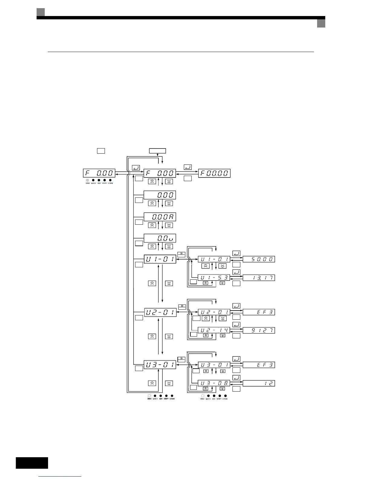
The Inverter can be operated in the Drive Mode. Monitor parameters, fault information and the fault history
parameters can be displayed.
When b1-01 (Reference selection is set to 0, the frequency reference can be changed from the frequency set-
ting display. Use the Increment, Decrement and Shift/RESET keys to change it. The set value will be accepted
when the DATA/ENTER key has been pressed.
Example Operations with LED Digital Operator
Fig 3.6 shows mode transition examples with the LED digital operator.
Fig 3.6 Operations in Drive Mode with LED Digital Operator
Drive Mode
Frequency reference
Output frequency
Output current
Monitor setting for o1-01
Status Monitor
Fault Trace
Fault History
Frequency reference setting/
display unit 01-03
Frequency reference
Fan operating time
Current error
Operating time at error
1st previous error
ESC
MENU
RESET
ESC
ESC
ESC
ESC
ESC
ESC
ESC
RESET
RESET
ESC
ESC
ESC
ESC
ESC
ESC
ESC
ESC
ESC
ESC
Power ON
ESC
Mode Selection Display Monitor Parameter Display Frequency Setting Display
Frequency Reference
Output Frequency
Output Current
Monitor setting set by o1-01
Status Monitor
Fault Trace
Fault History
Operating time at 4th latest
error
Previous error
Operating time at error
Current error
PI Feedback 2
Frequency Reference
Frequency Reference Setting /
Display unit set by 01-03
 Loading...


