5-20
Motor Parameters: E
V/f Pattern: E1
Param-
eter
Num-
ber
Name Description
Setting
Range
Factory
Setting
Change
during
Opera-
tion
Access
Level
MEMO-
BUS
Register
Page
E1-01
Input voltage set-
ting
Sets the Inverter input voltage.
This setting is used as a reference value
for protection functions.
155 to
255
*1
*1. Values for 200 V class Inverters are shown. For a 400 V class Inverter the values have to be doubled.
200 V
*1
No Q 300H
6-100
6-19
E1-03
V/f pattern selec-
tion
0 to E: Select from the 15 preset
patterns.
F: Custom user-set pattern
(Applicable for setting of E1-
04 to E1-10.)
FF: Custom user-set pattern with-
out voltage and frequency lim-
its
0 to F,
FF
F No A 302H 6-100
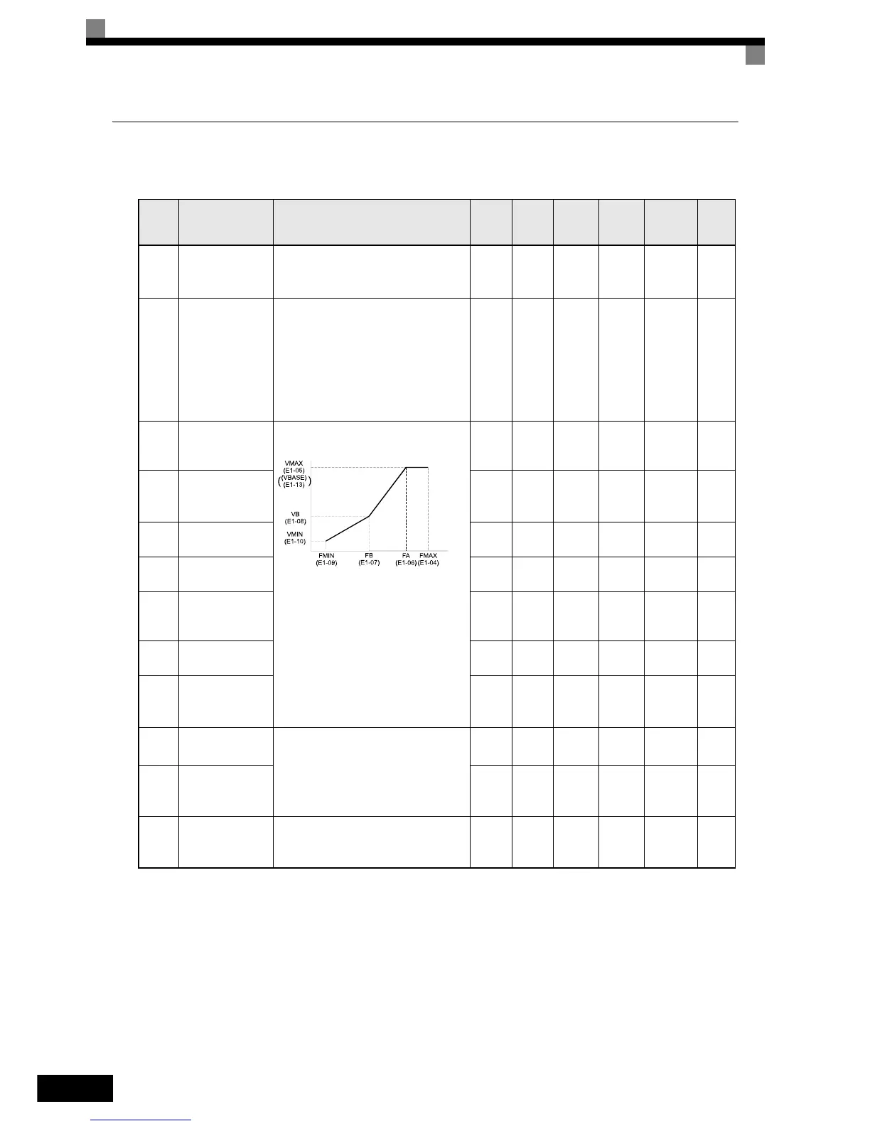
E1-04
Max. output fre-
quency
(FMAX)
To set V/f characteristics in a straight
line, set the same values for E1-07 and
E1-09. In this case, the setting for E1-
08 will be disregarded.
Always ensure that the four frequen-
cies are set in the following manner:
E1-04 (FMAX) ≥ E1-06 (FA) > E1-07
(FB) ≥ E1-09 (FMIN)
0.0 to
200.0
50.0
Hz
No A 303H 6-100
E1-05
Max. output volt-
age (VMAX)
0.0 to
255.0
*1
200.0
V
*1
No A 304H 6-100
E1-06
Base frequency
(FA)
0.0 to
200.0
50.0
Hz
No A 305H 6-100
E1-07
Mid. output fre-
quency (FB)
0.0 to
200.0
2.5 Hz No A 306H 6-100
E1-08
Mid. output fre-
quency voltage
(VB)
0.0 to
255
*1
15.0 V
*1
No A 307H 6-100
E1-09
Min. output fre-
quency (FMIN)
0.0 to
200.0
1.2 Hz No A 308H 6-100
E1-10
Min. output fre-
quency voltage
(VMIN)
0.0 to
255.0
*1
9.0 V
*1
No A 309H
4-11
6-100
E1-11
Mid. output fre-
quency 2
Set only to fine-adjust V/f for the out-
put range. Normally, this setting is not
required.
0.0 to
200.0
0.0 Hz
*2
*2. Parameters E1-11 and E1-12 are disabled when set to 0.0
No A 30AH 6-100
E1-12
Mid. output fre-
quency voltage 2
0.0 to
255.0
*1
0.0 V
*2
No A 30BH 6-100
E1-13
Base voltage
(VBASE)
Sets the output voltage of the base fre-
quency (E1-06).
0.0 to
255.0
*1
0.0 V
No A 30CH 6-100
Output Voltage (V)
Frequency (Hz)
 Loading...


