2-38
Installing and Wiring Option Cards
Option Card Models
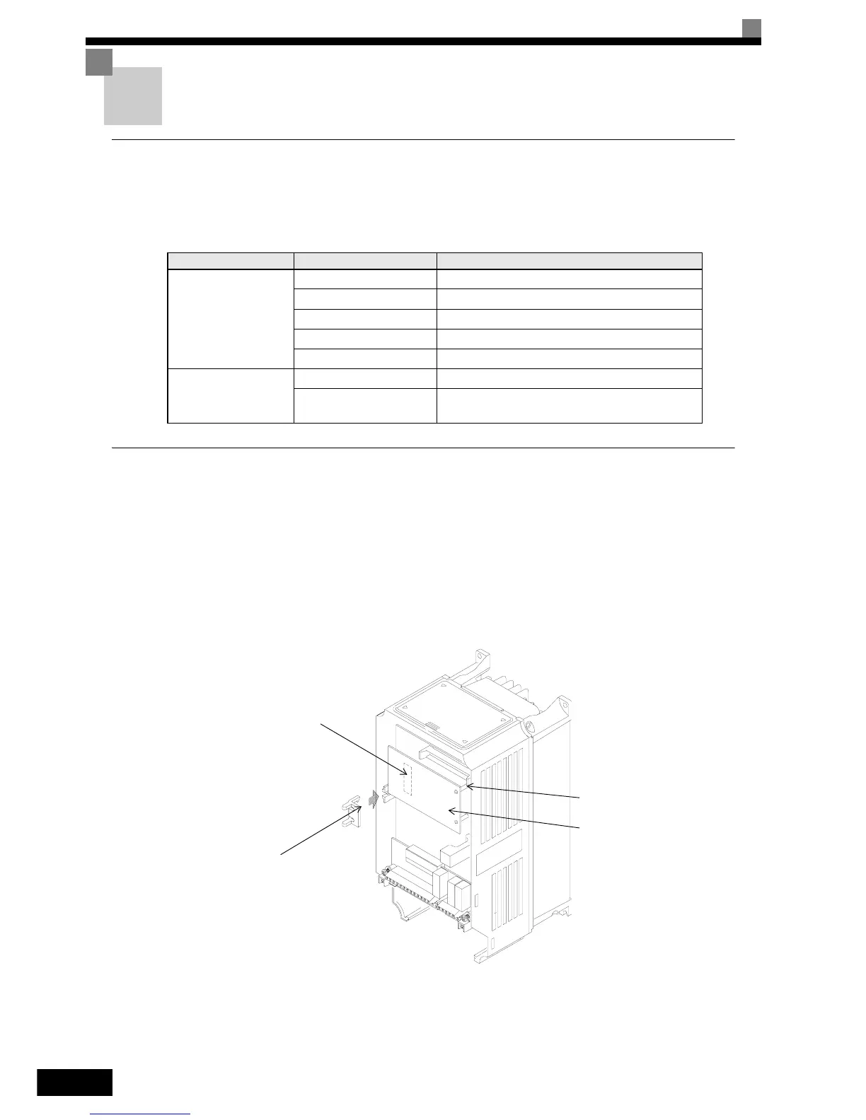
Option cards for field bus communications can be mounted in the Inverter like shown in Fig 2.22.
Table 2.16 lists the type of Option Cards and their specifications.
Installation in IP00 and NEMA 1 / IP20 Inverters
Before mounting an Option Card, remove the terminal cover and be sure that the charge indicator inside the
Inverter does not glow anymore. After that remove the Digital Operator, front cover and the option clip. Then
mount the Option Card.
Preventing Option Card Connectors from Rising
After installing the Option Card insert the Option Clip to prevent the side with the connector from rising. The
Option Clip can be easily removed before installing the card by holding onto the protruding portion of the Clip
and pulling it out.
Fig 2.22 Mounting Option Cards
Table 2.16 Option Cards
Card Model Specifications
Communication cards
3G3RV-PDRT2 Intelligent DeviceNet option card
SI-P1 Option card for Profibus-DP fieldbus
SI-R1 Option card for InterBus-S fieldbus
SI-S1 Option card for CANopen fieldbus
SI-J Option card for LONworks
PLC Option Card
3G3RV-P10ST8-E PLC option card
3G3RV-P10ST8-DRT-E
PLC option card with DeviceNet communications
port (Slave)
CN2
C Option Card connector
Option Clip
(To prevent raising of
C Option Card)
C Option Card mounting space
 Loading...


