Adjusting Frequency References
6-21
Adjusting Frequency References
Adjusting Analog Frequency References
The analog reference values can be adjusted using the gain and bias functions for the analog inputs.
Related Parameters
Adjusting Analog Frequency Reference Using Parameters
The frequency reference can be input from the control circuit terminals using analog voltage or current signals
(analog input A2 only).
The input signal levels can be selected using
• H3-01 for the analog input A1
• H3-08 for the analog input A2
Adjustments to the signals can be made using:
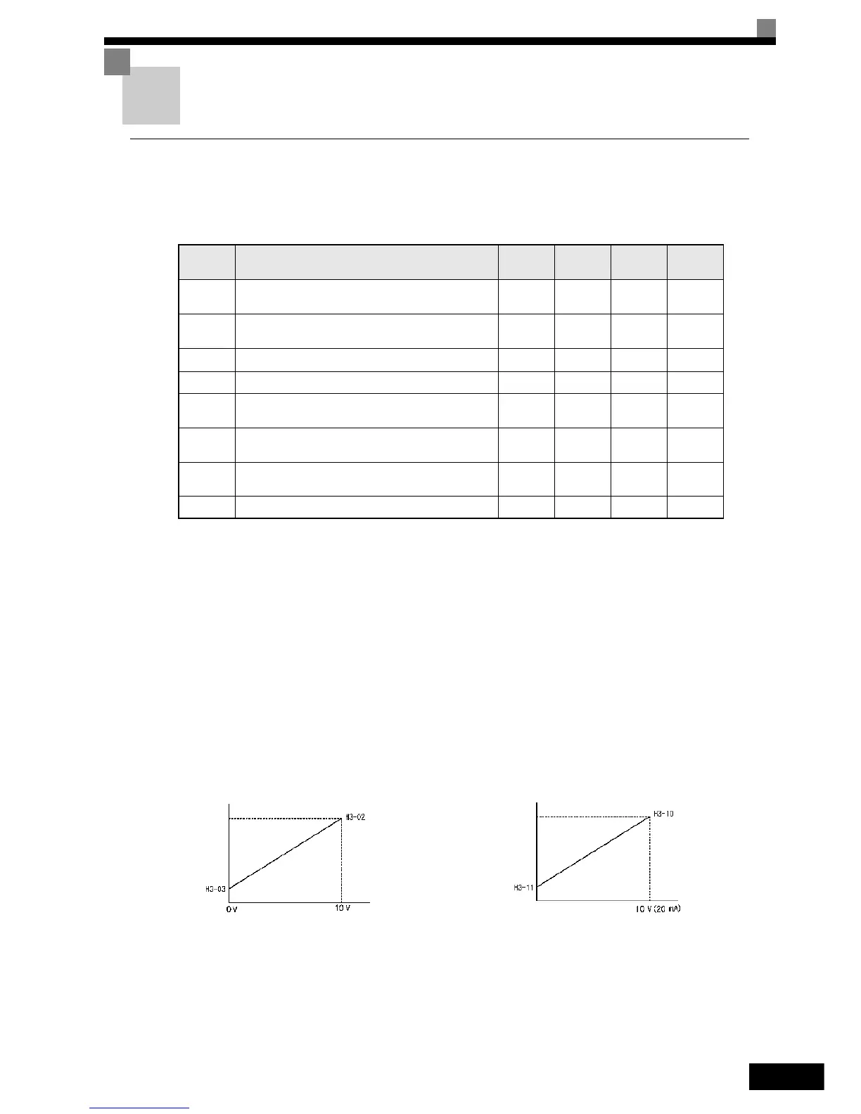
• H3-02 (Gain) and H3-03 (Bias) if analog input A1 is selected to be the frequency reference input
• H3-10 (Gain) and H3-11 (Bias) if analog input A2 is selected to be the frequency reference input
Refer to Fig 6.23 for adjusting the signal using the gain and bias functions.
Fig 6.23 Terminals A1 and A2 Inputs
Parameter
Number
Name
Setting
Range
Factory
Setting
Change
during
Operation
Access
Level
H3-02 Frequency reference terminal A1 input gain
0.0 to
1000.0
100.0% Yes A
H3-03 Frequency reference terminal A1 input bias
-100.0
to +100.0
0.0% Yes A
H3-08 Multi-function analog A2 signal level selection 0, 2, 3
2
*1
*1. The setting is automatically switched to “B” when the PI controller is enabled
No
A
*2
*2. Parameter is moved to Quick Programming Mode when PI controller is enabled.
H3-09 Multi-function analog A2 function selection 0 to 16 0 No
A
*2
H3-10 Multi-function analog A2 input gain
0.0 to
1000.0
100.0% Yes A
H3-11 Multi-function analog A2 input bias
-100.0
to +100.0
0.0% Yes A
H3-12 Analog input filter time constant
0.00 to
2.00
0.30 sec. No A
H3-13 Terminal A1/A2 switching 0 or 1 0 No
A
*2
Frequency reference
Terminal A1 input
Terminal A1
input voltage
Frequency reference
Terminal A2 input
Terminal A2 input
voltage (current)
0V (4 mA/0 mA)
 Loading...


