2-18
Standard Connection Diagrams
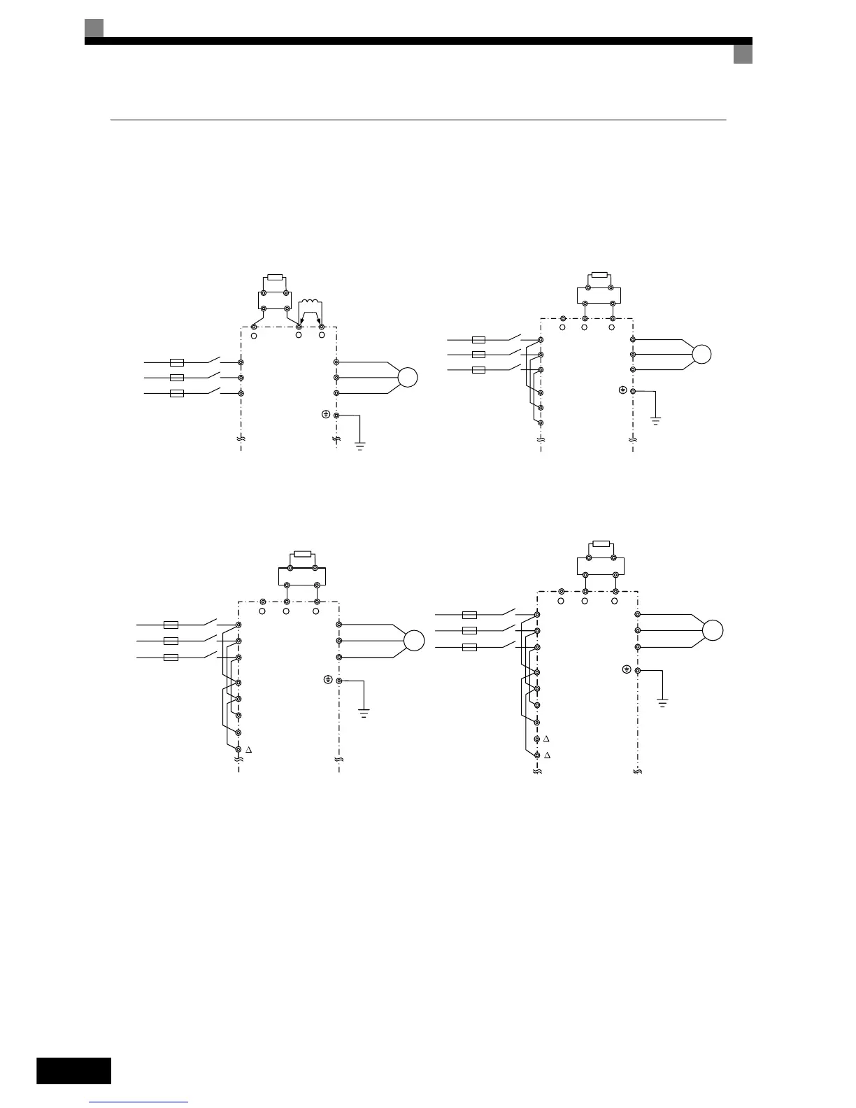
Standard Inverter (NEMA 1 / IP20) connection diagrams are shown in Fig 2.7. These are the same for both
200 V Class and 400 V Class Inverters. Fig 2.8 shows the standard Inverter connection diagrams for the IP54
Inverters. The connections depend on the Inverter capacity.
Control power is supplied internally from the DC bus at all inverter models.
Fig 2.7 Main Circuit Terminal Connections for NEMA 1 / IP20 Inverters
CIMR-E7Z20P4 to 2018
and 40P4 to 4018
Be sure to remove the short-circuit bar before connecting the DC reac-
tor.
CIMR-E7Z2022, 2030
and 4022 to 4055
The DC reactor is built in.
CIMR-E7Z2037 to 2110 CIMR-E7Z4075 to 4300
+
1
+
2
R/L1
S/L2
T/L3
U/T1
V/T2
W/T3
M
3 Phase 200VAC or
400VAC
DC reactor
(optional)
CDBR Braking
Unit (optional)
Braking
Resistor (optional)
-
+
1
-+
3
R/L1
S/L2
T/L3
U/T1
V/T2
W/T3
M
3 Phase 200VAC or
400VAC
CDBR Braking
Unit (optional)
Braking
Resistor (optional)
R1/L11
S1/L21
T1/L31
+
1
-+
3
R/L1
S/L2
T/L3
U/T1
V/T2
W/T3
M
3 Phase 200VAC or
400VAC
CDBR Braking
Unit (optional)
Braking
Resistor (optional)
R1/L11
S1/L21
T1/L31
r / l1
/ l2
+
1
-+
3
R/L1
S/L2
T/L3
U/T1
V/T2
W/T3
M
3 Phase 200VAC or
400VAC
CDBR Braking
Unit (optional)
 Loading...


