Wiring Control Circuit Terminals
2-35
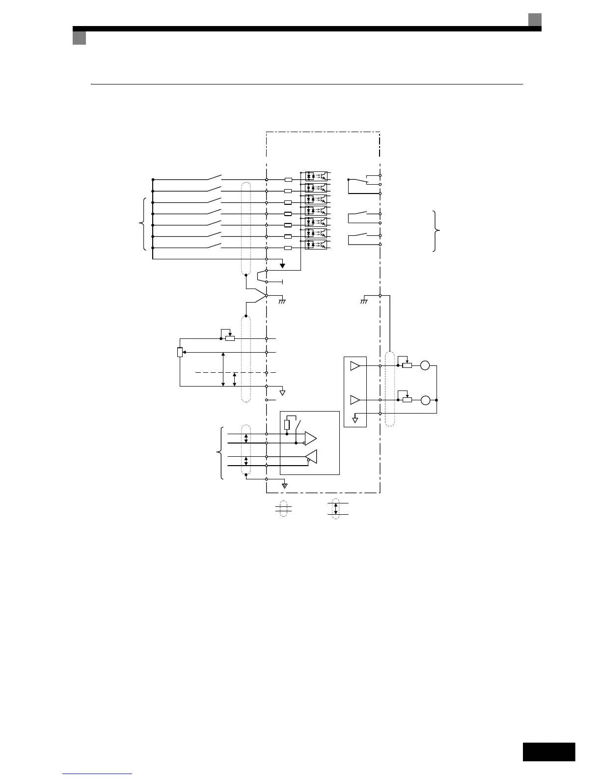
Control Circuit Terminal Connections
Connections to Inverter control circuit terminals are shown in Fig 2.21.
Fig 2.21 Control Circuit Terminal Connections
M2
M1
MC
MB
MA
S1
S3
S4
S5
S6
S7
SN
SC
SP
24V
+V
AC
A2
A1
0V
E(G)
PP
4 to 20mA
0 to 10V
3
2k
E(G)
FM
+
-
AM
+
-
AC
AM
FM
R+
R-
S+
S-
IG
P
P
P
2
1
-V
M4
M3
Ω
2k
Ω
Reverse Run/Stop
External fault
Fault reset
Multi-step speed setting 1
Multi-step speed setting 2
Jog frequency selection
Multi-function
digital inputs
[Factory settings]
Analog input 1: Master
frequency reference
0 to 10 V (20 k )
Analog input power supply
+15 V, 20 mA
Multi-function analog input 1:
[Default: Frequency Bias
4 to 20 mA (250 )]
Ω
Ω
Analog input power supply
-15 V, 20 mA
Terminating
resistance
MEMOBUS
communication
RS-485/422
Shielded wires
Twisted-pair
shielded wires
Multi-function analog output 1
(0 to 10 V, 2 mA)
[Default: Output frequency, 0 to 10 V]
Multi-function analog output 2
(0 to 10 V, 2 mA)
[Default: Output current, 0 to 10 V]
Fault contact output
250 VAC, 1 A max.
30 VDC, 1 A max.
Contact output 1
[Default: During run]
Contact output 2
[Default: Zero speed]
Multi-function digital
output
250 VAC, 1 A max.
30 VDC, 1 A max.
Adjustment,
20 k
Ω
Adjustment,
20 k
Ω
Shield
terminal
Shield
terminal
Adjustment
Forward Run/Stop
S2
≈
≈
Varispeed E7
CIMR-E7Z47P5
 Loading...


