6-48
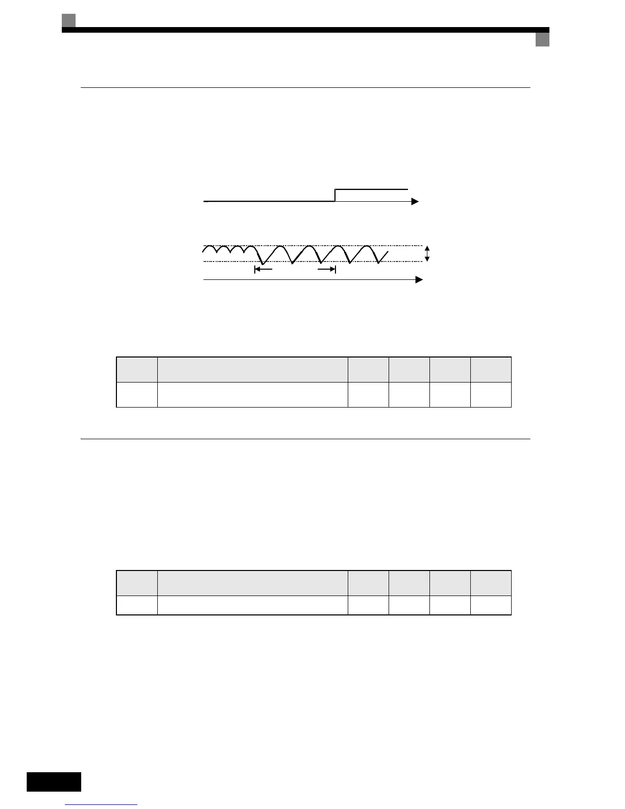
Input Phase Loss Detection Level
For the Input Phase Loss Detection the drive monitors the DC bus ripple. The drive integrates this ΔV value
over 10 scans (appr. 10 seconds). If the integrated ΔV value of any consecutive ten scan range is greater than
the voltage determined by multiplying L8-06 times the drives rated OV Trip point (400 VDC/800 VDC), a PF
fault will occur and the Drive will coast to stop.
Fig 6.39 Input Phase Loss Detection
Related Parameters
Ground Fault Protection
The ground fault protection function detects the earth leakage current by calculating the sum of the three out-
put currents. Normally this sum should be 0. If the sum exceeds 50% of the Inverter rated current a GF fault is
detected and the motor coasts to stop.
The ground fault protection can be disabled by setting L8-09 to 0. It is not recommended to disable the ground
fault protection.
Related Parameters
Parameter
Number
Name
Setting
Range
Factory
Setting
Change
during
Operation
Access
Level
L8-06 Input Phase Loss Detection Level
0.0 to
25.0%
5.0%
*1
*1. The factory setting depends on the Inverter capacity. The value for a 200 V class Inverter of 0.4 kW is given.
No A
Parameter
Number
Name
Setting
Range
Factory
Setting
Change
during
Operation
Access
Level
L8-09 Ground fault protection selection 0 or 1 1 No A
t
L8-06
Phase Loss Fault
Signal
DC Bus
Voltage
10 seconds
 Loading...


