Machine Protection
6-33
Motor Overload Protection
The motor can be protected from overload using the Inverter's built-in electronic thermal overload relay func-
tion (I²t calculation).
Related Parameters
Multi-Function Outputs (H2-01 to H2-02)
Setting Motor Rated Current (E2-01)
Set the rated current value on the motor nameplate in parameters E2-01. This set value is the base current for
the internal thermal overload calculation.
Setting Motor Overload Protection Characteristics (L1-01)
Set the overload protection function in L1-01 according to the application.
Set L1-01 to:
0: to disable the thermal motor protection function.
1: to enable the thermal motor protection for a fan cooled general purpose motor (self-cooled).
2: to enable the thermal motor protection for Inverter motors (forced or externally cooled)
3: to enable the thermal motor protection for a special vector motor (externally cooled).
Application Precautions
• If a multi-function digital output is programmed to 1F the output will stay switched ON as long as the
motor is overloaded. When the motor has been stopped to cool down the output will be switched OFF as
soon as the Inverter’s I² t calculation falls below 90% of the detection level.
• The multi-function digital output programmed to 1F will also switch OFF when the Inverter itself is in
fault condition. The fault has to be reset manually.
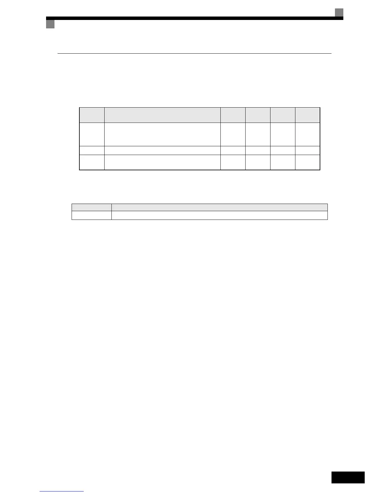
Parameter
Number
Name
Setting
Range
Factory
Setting
Change
during
Operation
Access
Level
E2-01 Motor rated current
0.32 to
6.40
*1
*1. The setting range is 10% to 200% of the Inverter rated output current. The value for a 200 V class Inverter of 0.4kW is given.
1.90 A
*2
*2. The factory setting depends on the Inverter Capacity. The value for a 200 V class Inverter of 0.4 kW is given.
No Q
L1-01 Motor protection selection 0 to 3 1 No A
L1-02 Motor protection time constant
0.1 to
5.0
1.0 min No A
Set Value Function
1F During motor overload (OL1, including OH3) pre-alarm (ON: 90% or more of the detection level)
 Loading...


