6-70
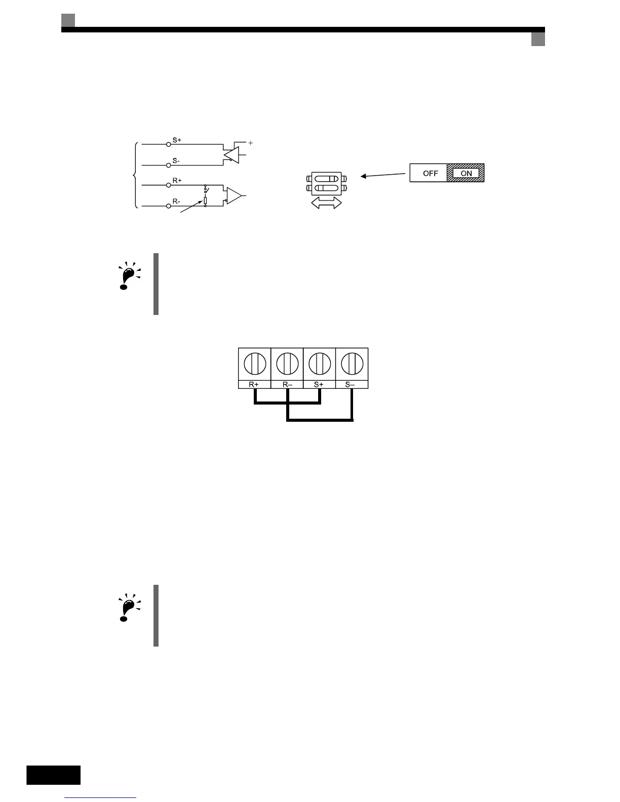
Communications Connection Terminal
The MEMOBUS communication uses the following terminals: S+, S-, R+, and R-. Enable the terminating
resistance by turning ON pin 1 of switch S1 for the last Inverter (seen from the PLC) only.
Fig 6.51 Communications Connection Terminal
Fig 6.52 Connections when RS485 Communication is used
Procedure for Communicating with the PLC
Use the following procedure to perform communications with the PLC.
1. Turn OFF the power supply and connect the communications cable between the PLC and the Inverter.
2. Turn ON the power supply.
3. Set the required communications parameters (H5-01 to H5-08) using the Digital Operator.
4. Turn OFF the power supply and check that the Digital Operator display has completely disappeared.
5. Turn ON the power supply once again.
6. Perform communications with the PLC.
IMPORTANT
• Separate the communications cables from the main circuit cables and other wiring and power cables.
• Use shielded cables for the communications cables and use proper shielding clamps
• When using RS485 communication is used, connect S+ to R+, and S- to R-, on the Inverter exterior.
See Fig 6.52 below.
IMPORTANT
It is absolutely necessary to cycle the input power once when any of the serial communication parame-
ters (H5-01 to H5-09) has been changed.
Terminating resistance (1/2W, 110 Ohms)
-
RS-422A or
RS-485
S1
S1
O
F
F
1
2
Terminating
resistance
 Loading...


