User Parameter Tables
5-41
Monitor Parameters: U
Status Monitor Parameters: U1
Param-
eter
Number
Name Description
Output Signal Level During Multi-
Function Analog Output
Min.
Unit
MEMO-
BUS
Register
U1-01
Frequency refer-
ence
Monitors/sets the frequency ref-
erence value.
*1
10 V: Max. frequency
0.01
Hz
40H
U1-02 Output frequency
Monitors the output frequency.
*1
10 V: Max. frequency
0.01
Hz
41H
U1-03 Output current Monitors the output current.
10 V: Inverter rated output
current
0.01
A
42H
U1-06 Output voltage
Monitors the output voltage
reference.
10 V: 200 VAC (400 VAC)
0.1
V
45H
U1-07 DC bus voltage Monitors the DC bus voltage. 10 V: 400 VDC (800 VDC) 1 V 46H
U1-08 Output power Monitors the output power.
10 V: Inverter capacity
(max. applicable motor
capacity)
0.1
kW
47H
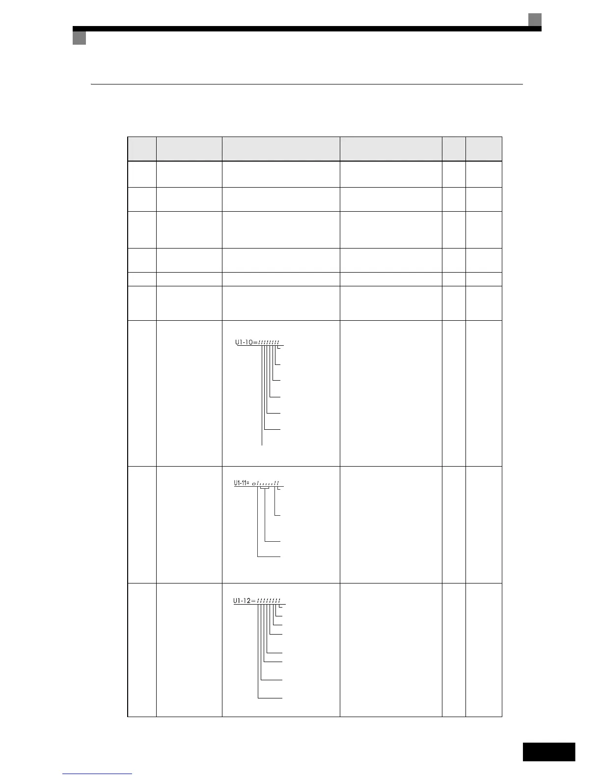
U1-10
Input terminal
status
Shows input ON/OFF status.
(Cannot be output.) – 49H
U1-11
Output terminal
status
Shows output ON/OFF status.
(Cannot be output.) – 4AH
U1-12 Operation status
Inverter operating status.
(Cannot be output.) – 4BH
1: FWD command
(S1) is ON
1: REV command
(S2) is ON
1: Multi input 1
(S3) is ON
1: Multi input 2
(S4) is ON
1: Multi input 3
(S5) is ON
1: Multi input 4
(S6) is ON
1: Multi input 5
(S7) is ON
1: Multi-function
digital output 1
(M1-M2) is ON
1: Multi-function
digital output 2
(M3-M4) is ON
Not used
(Always 0).
1: Error output
(MA/MB-MC) is
ON
1: Run
1: Zero speed
1: Reverse
1: Reset signal
input
1: Speed agree
1: Inverter ready
1: Minor fault
1: Major fault
 Loading...


