6-86
Using the Timer Function
The digital input and output terminals can be used with a timer function: A digital output is switched ON with
a set delay time after a digital input has been switched ON.
Related Parameters
Multi-Function Digital Inputs (H1-01 to H1-05)
Multi-Function Digital Outputs (H2-01 to H2-02)
Setting Example
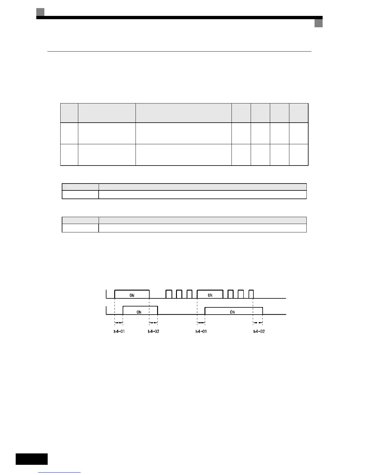
When the timer function input remains switched ON for a time longer than the setting in b4-01, the timer out-
put function is turned ON. When the timer function input remains switched OFF for a time longer than the set-
ting in b4-02, the timer output function is turned OFF. An example of timer function operation is given in the
following diagram.
Fig 6.55 Timer Function Operation Example
Param-
eter
Number
Name Description
Setting
Range
Factory
Setting
Change
during
Opera-
tion
Access
Level
b4-01
Timer function ON-delay
time
Set the timer function output ON delay time (dead
time) for the timer function input in 1-second units.
Enabled when a timer function is set in H1-
and H2-.
0.0 to
300.0
0.0 sec. No A
b4-02
Timer function OFF-delay
time
Set the timer function output OFF delay time (dead
time) for the timer function input in 1-second units.
Enabled when the timer function is set in H1-
and H2-.
0.0 to
300.0
0.0 sec. No A
Set Value Function
18 Timer function input
Set Value Function
12 Timer function output
Timer function input
Timer function output
 Loading...


