4-4
Checking the Display Status
After normal power up without any faults the operator display will show the following depending on the
operator.
Display with LED Digital Operator
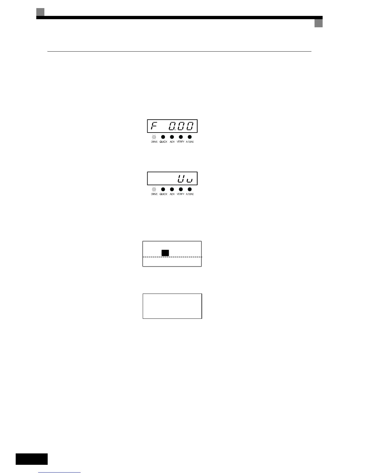
After normal power up without any faults the operator display will show the following:
When a fault has occurred, the details of the fault will be displayed instead of the above display. In that case,
refer to Chapter 7, Troubleshooting. The following display is an example of a display for faulty operation.
Display with LCD Digital Operator
After normal power up without any faults the operator display will show the following:
When a fault has occurred, the details of the fault will be displayed instead of the above display. In that case,
refer to Chapter 7, Troubleshooting. The following display is an example of a display for faulty operation.
Display for normal operation
The frequency reference monitor is dis-
played in the data display section.
Display for fault operation
The display will differ depending on the
type of fault.
A low voltage alarm is shown at left.
Display for normal operation
The frequency reference monitor is dis-
played in the data display section.
Display for fault operation
The display will differ depending on the
type of fault.
A low voltage alarm is shown at left.
Frequency Ref
-DRIVE-
U1-02= 0.00Hz
U1-03= 0.00A
Rdy
U1- 01=50.00Hz
-DRIVE-
UV
Main Power Loss
 Loading...


