Maintenance and Inspection
8-7
Removing and Mounting the Control Circuit Terminal Card
Removing the Control Circuit Terminal Card
1. Remove the Digital Operator and front cover.
2. Remove the connecting line connectors connected to FE and NC on the control circuit terminal card.
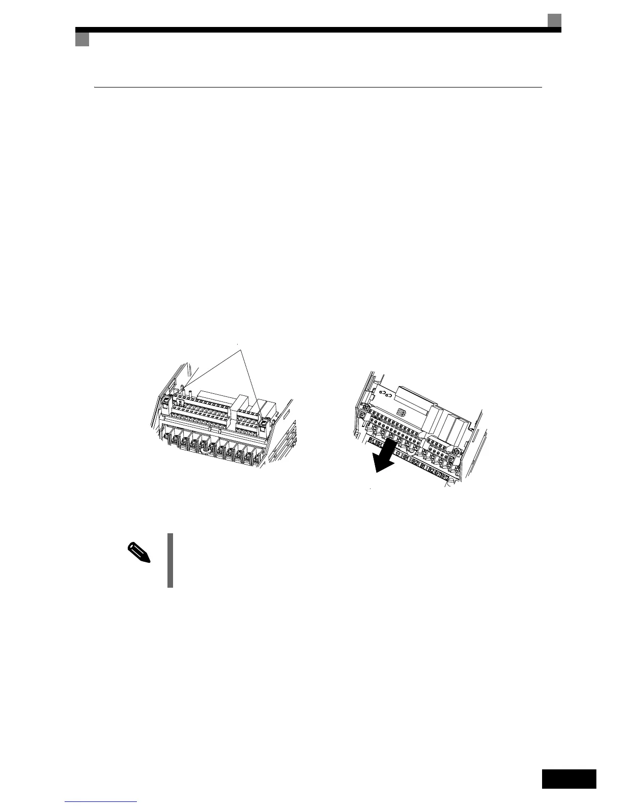
3. Loosen the mounting screws (1) on the left and right sides of the control terminals until they are free. (It is
not necessary to remove these screws completely. They are self-rising.)
4. Pull the terminal card out downwards (in direction 2).
Mounting the Control Circuit Terminal Card
Use the removal procedure in reverse order to mount the terminal card.
Confirm that the terminal circuit card and the controller card properly meet at connector CN5 before pressing
into its plan.
The connector pins may be bent if the card is forced into place!
Fig 8.3 Removing the Control Circuit Terminal Card
NOTE
Always confirm that the charge indicator does not light anymore before removing or mounting the con-
trol circuit terminal card.
Removing and Mounting the
Control Circuit Terminal Card
1
2
 Loading...


