Input Terminal Functions
6-55
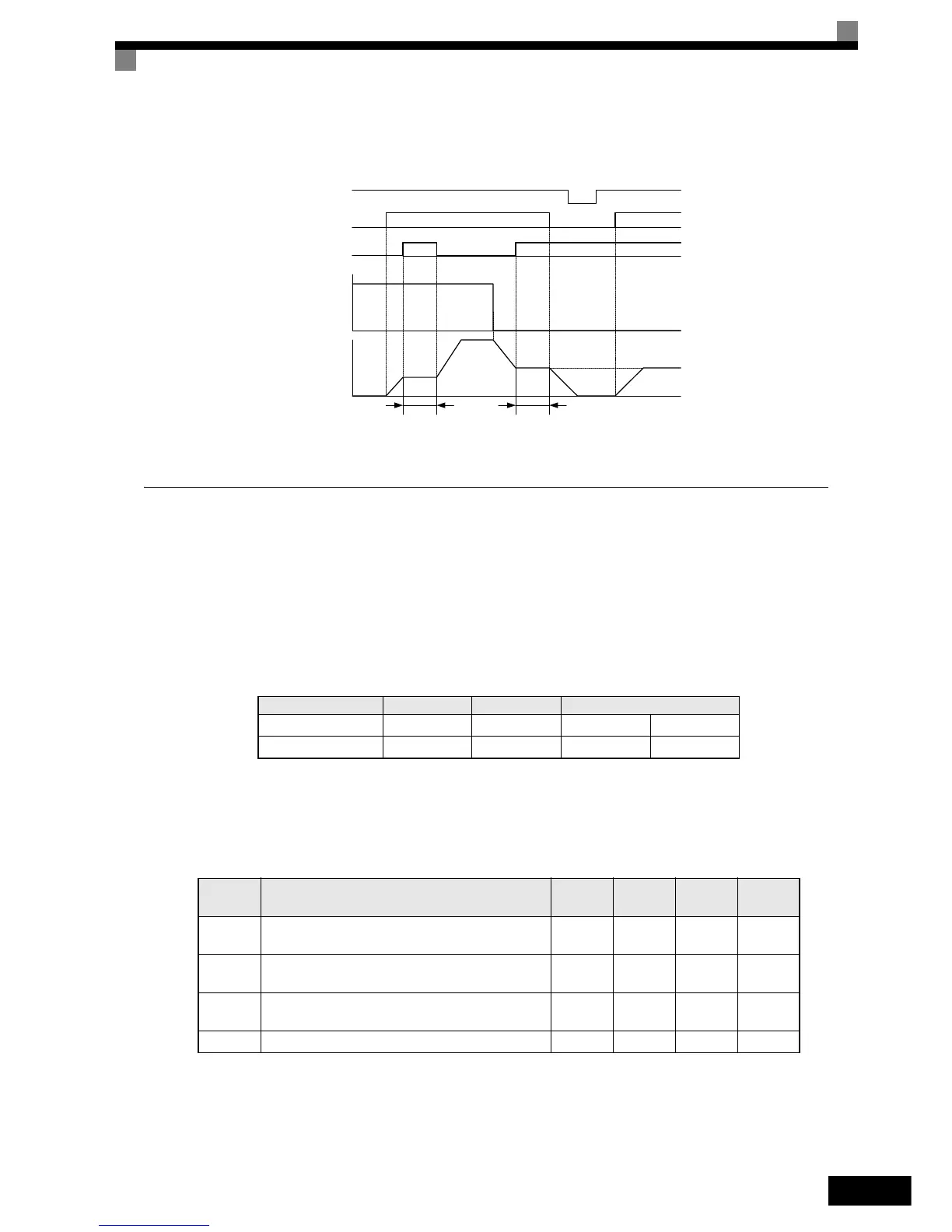
Time Chart
The time chart when using Acceleration/Deceleration Ramp Hold commands is given below.
Fig 6.43 Acceleration/Deceleration Ramp Hold
Raising and Lowering Frequency References Using Digital Input Signals
(UP/DOWN)
The UP and DOWN commands raise and lower Inverter frequency references by turning ON and OFF a multi-
function digital input terminal S3 to S7.
To use this function, set two of the parameters H1-01 to H1-05 (digital input terminal S3 to S7 function selec-
tion) to 10 (UP command) and 11 (DOWN command).
The table below shows the possible combinations of the UP and DOWN command and the corresponding
operation.
The change of the output frequency depends on the acceleration and deceleration times. Be sure to set b1-02
(Run command selection) to 1 (Control circuit terminal).
Related Parameters
Operation Acceleration Deceleration Hold
UP command ON OFF ON OFF
DOWN command OFF ON ON OFF
Parameter
Number
Name
Setting
Range
Factory
Setting
Change
during
Operation
Access
Level
d2-01 Frequency reference upper limit
0.0 to
110.0
100.0% No A
d2-02 Frequency reference lower limit
0.0 to
110.0
0.0% No A
d2-03 Master speed reference lower limit
0.0 to
110.0
0.0% No A
d4-01 Frequency reference hold function selection 0 or 1 0 No A
OFF
OFF ON OFF
OFF OFFON ON
ON
Power supply
Forward/Stop
Acceleration/Deceleration
Ramp Hold
Frequency reference
Output frequency
Hold Hold
 Loading...


