7 Protocol Decoding RIGOL
DS6000 User’s Guide 7-13
SPI Decoding (Option)
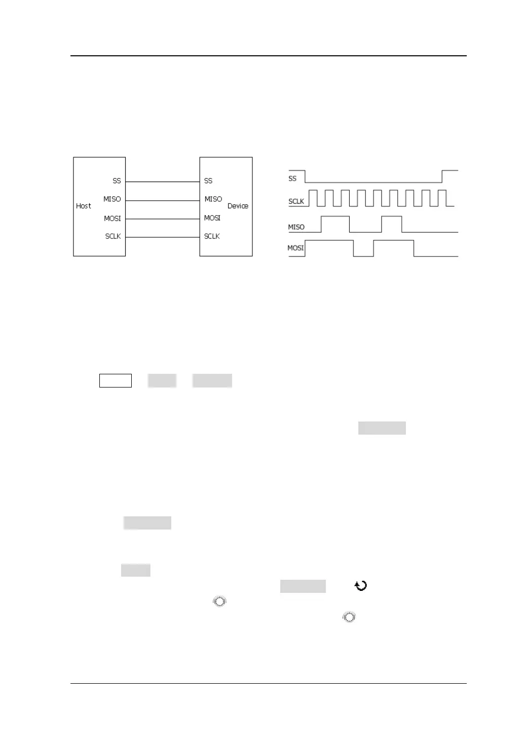
SPI serial bus consists of chip select line (SS), clock line (SCLK), MISO and MOSI.
SS: set the polarity to "Low" or "High". When SS selection is valid, the SPI bus
samples data from MISO and MOSI at the jumping point of SCLK.
SCLK: sample data from MISO and MOSI on the clock rising edge or falling edge.
MISO: master input/slave output. Set the polarity to "Low" or "High".
MOSI: master output/slave input. Set the polarity to "Low" or "High".
Press MATH BUS1 Decode to select "SPI" and turn the SPI decoding function
menu on.
If the current trigger type of the trigger system is SPI, press CopyTrig to copy the
current SPI trigger configurations (include the CS/timeout mode, clock channel, data
channel, data bits and etc.) to the SPI decoding configurations. After that, you can
still set the SPI decoding parameters according to the introductions below.
Note: The copy function is only available when the current trigger type is "SPI";
otherwise, CopyTrig is not available.
1. Decoding Mode Setting
Press Mode to select the "TimeOut" or "CS" decoding mode.
When "TimeOut" is selected, press TimeOut; use or the inner knob of
the navigation knob
to adjust the timeout time with a small step value
or rotate the outer knob of the navigation knob
to quickly adjust the
timeout time within a relatively larger range. (The greater the rotation
amplitude of the outer knob, the faster the variations in the values.) The
 Loading...