UM353-1B Data Mapping
April 2012
6-5
6.3 LOOP DATA
Loop data is grouped into several categories. When using Modbus, the groupings enable single data requests (up to
60 Words/Registers or 48 Coils) to obtain similar data with a single command. The loop will have different data if
assigned as a controller type (i.e. using the ODC block), a sequencer type (i.e. using the ODS block), an Analog
Indicator Display (i.e. using the ODA block), or a Discrete Indicator Display (i.e. using the ODD block), or
Pushbutton/Switch Operation (i.e. using the ODP block).
a) Dynamic data may change value on each controller scan and/or is not identified as being changed by the data
base change bit (coil). This category of data usually needs to be updated by a workstation every few seconds.
b) Variable data changes periodically. It is usually associated with on-line operation at a workstation but may only
need to be updated on a lower periodic basis or when a data base change is indicated.
c) Static data is similar to variable data but has a lower update requirement. The data may only need updating when
a change is indicated or to verify a previous change made to a parameter.
d) String data contains tag names, units, and messages.
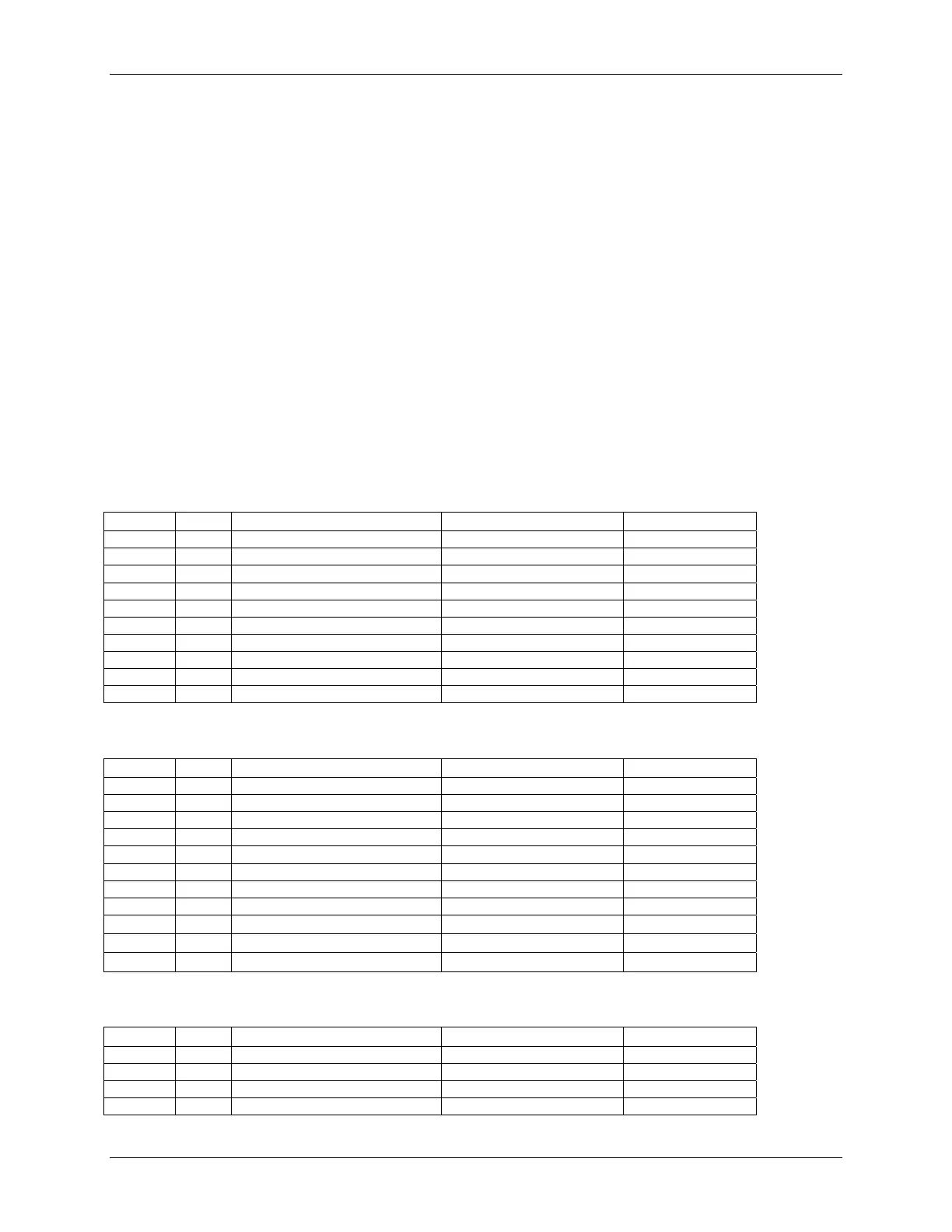
6.3.1 Dynamic Loop Integer Data
Controller [ODC]
Code R/W Description Range Register (MB)
L#PI R Process (%) -3.3 to 103.3 ($0-$0FFF) 40201+10(#-1)
L#SI R/W Setpoint (%) -3.3 to 103.3 ($0-$0FFF) 40202+10(#-1)
L#VI R/W Valve (%) -3.3 to 103.3 ($0-$0FFF) 40203+10(#-1)
L#XI R X Variable (%) -3.3 to 103.3 ($0-$0FFF) 40204+10(#-1)
L#YI R Y Variable (%) -3.3 to 103.3 ($0-$0FFF) 40205+10(#-1)
L#RI R/W Ratio 0.00 to 38.40($80-$0F80) 40206+10(#-1)
L#BI R/W Bias 100-0-100 ($80-$0F80) 40207+10(#-1)
L#TlmI R Totalizer - 3 ms (whole) digits 0-999 ($0000-$03E7) 40208+10(#-1)
L#TllI R Totalizer - 3 ls (whole) digits 0-999 ($0000-$03E7) 40209+10(#-1)
L#PCSW R PCOM Block Status Word (V1.3) 1-7 ($0001-$0007) 40210+10(#-1)
Sequencer [ODS]
Code R/W Description Range Register (MB)
L#SSNI R Sequencer Step No. 0-250 ($0000-$00FA) 40201+10(#-1)
L#SNSI R Sequencer Number of Steps 0-250 ($0000-$00FA) 40202+10(#-1)
L#SNGI R Sequencer Number of Groups 0-16 ($0000-$0010) 40203+10(#-1)
L#SLS R/W Sequencer Loop Status (see SLS) (see coils)
L#SNRI R Sequencer Number of Recipes 0-9 ($0000-$0009) 40204+10(#-1)
L#CRNI R/W Current Recipe Number 0-9 ($0000-$0009) 40205+10(#-1)
L#PCSW
R PCOM Block Status Word 1-7 ($0001-$0007) 40206+10(#-1)
L#TACM
R Total Active Conditional Msgs 0-64 $0000-$0040) 40207+10(#-1)
(spare) 0 ($0000) 40208+10(#-1)
….. ….. ….. ….. …..
(spare) 0 ($0000) 40210+10(#-1)
Analog Indicator [ODA]
Code R/W Description Range Register (MB)
L#P1I R Process 1 (%) -3.3 to 103.3 ($0-$0FFF) 40201+10(#-1)
L#P2I R Process 2 (%) -3.3 to 103.3 ($0-$0FFF) 40202+10(#-1)
L#P3I R Process 3 (%) -3.3 to 103.3 ($0-$0FFF) 40203+10(#-1)
L#P4I R Process 4 (%) -3.3 to 103.3 ($0-$0FFF) 40204+10(#-1)