Installation UM353-1B
April 2012
7-12
3. Crimp-On Connector - Insert the resistor lead and any signal wiring into the
connector until the wire ends are visible at the pin end of the connector.
Use a standard electrical connector crimp tool to crimp the connection. Be
certain that all resistor leads and signal input wires are inserted in the
connector before crimping.
4. Loosen the two terminal screws using a straight blade screwdriver with a 1/8" (3 mm) blade width. Insert
wires, resistor leads, or a crimp-on connector pin into the two openings in the side of the connector adjacent to
the selected terminal numbers.
5. Check that all involved components and station wiring are fully inserted and carefully tighten the screws to 5
in. lbs. Do not over tighten.
6. Repeat steps 1-5 for each 4-20 mA, 1-5 Vdc and millivolt input.
7. Carefully dress resistors and wiring so that excessive stress is not placed on a component, wire, or connection.
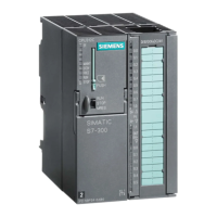
7.4.3 Analog Output Wiring (4-20 mA, 1-5 Vdc)
Analog output functions blocks are AOUT1, AOUT2, and AOUT3. Figure 7-9 shows connections for an external
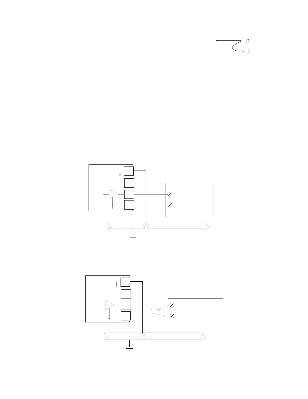
device that accepts 4-20 mA. For an external device that needs 1-5 Vdc, see Figure 7-10. Refer to Section 7.4.1 for
wiring guidelines.
6
17
Common Ground Bus
Earth
Ground
18*
Controller Circuitry
MG00505c
Station Common
PS2 or Model 760
Valve Positioner,
Model 77 or 771
I/P Transducer,
or Other 4-20 MA
Device
+
_
+
_
Model 353
Rear Terminals**
4-20 mA
* Or any station common terminal
** See Table 7-1 for AOUT2 and AOUT3 terminals
Figure 7-9 Analog Output AOUT 1, Current Output
6
17
Common Ground Bus
Earth
Ground
18*
* Or any station common terminal
** See Table 7-1 for AOUT2 and AOUT3 terminals.
Controller Circuitry
MG00505c
Station Common
+
_
+
_
Model 353
Rear Terminals**
1-5 Vdc
SIREC D Recorder
or Other 1-5 Vdc
Device
Figure 7-10 Analog Output AOUT1, Voltage Output
MG000631
Range Resistor
Signal Input Wire
Crimp-On
Connector

 Loading...