Software Release Memo
Siemens Industry, Inc.
SR353-15
Rev: 2
September 2012
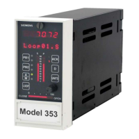
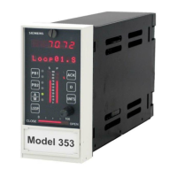
Model 353 Process Automation Controller
Design Level “B”
MPU Controller Board Firmware Version 4.03
PRODUCT(S) INVOLVED
Model 353, Design Level B
1
, Process Automation Controller (e.g. TGX:353_ _ _ _ _ _B_)
INTRODUCTION
This Software Release memo discusses the enhancements and operational considerations for version 4.03 of MPU
Controller board firmware. This firmware is intended for a Design Level “B” Model 353 with 4.00, 4.01, or 4.02
firmware.
Firmware is installed using the Controller Firmware Upgrade Utility, version 4.03, available for download from
http://support.automation.siemens.com/US/view/en/51785815. The download includes the Upgrade Utility and
controller firmware. For more information about the utility and firmware installation steps, refer to Software
Release memo SR15939-71-6.
ENHANCEMENTS
The following enhancements are included in version 4.03 firmware:
Universal T/C inputs – At power up, a design level “B” 353 controller with an I/O Expander Board will now
correctly clear an error status retained from the previous session.
Faceplate buttons UNITS and TAG now require only a single press to update the faceplate display. Previously more
that one press could be needed.
OPERATIONAL CONSIDERATIONS
In the STATN - Station Parameters function block, parameters CONFG LO and PARAM LO can have a value of
either 0
or
1, 2, or 3: a 0 allows writes, a 1, 2, or 3 prevents writes. (There is no difference in operation in selecting a
1, 2, or 3.) Earlier User’s Manuals list “write” values as YES/NO, which was correct for earlier firmware. Later
manuals list values (1, 2, or 3) incorrectly. Reads are always enabled.
Simultaneously pressing faceplate buttons PB1 and PB2 will cause the loop A/M status to toggle, even if the PB1
and PB2 function blocks are not configured.
1
The design level is indicated by the next to last character in the model number. The characters shown are those
required to identify an involved instrument. See the Siemens Process Instruments catalog or the instrument’s User’s
Manual (UM353-1B) for complete model designation information.

 Loading...


