UM353-1B Installation
April 2012
7-5
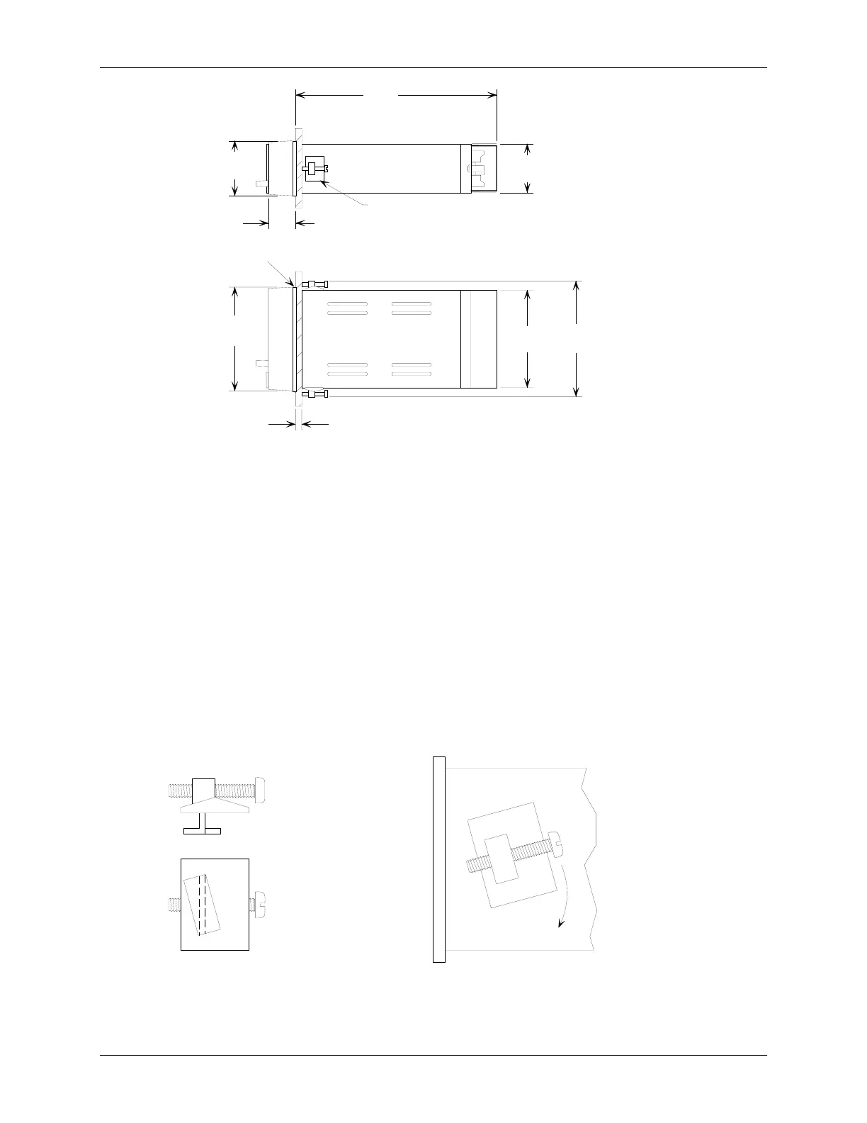
2.84
(72)
11.25
(285.8)
2.67
(67.8)
1.18
(30)
Mounting Clip
TOP VIEW
5.67
(144)
5.42
(137.7)
6.3
(160)
0.32
(0.8)
Max.
SIDE VIEW
MG00391a
Case
Flange
Dimensions in inches (millimeters)
Figure 7-3 Siemens 353 Dimensions
7.3.3 Station Mounting
A straight slot screwdriver with at least a 10" (254 mm) shank is needed to tighten the two mounting clip screws.
1. Locate the supplied Mounting Clip Kit. It contains two mounting clips and two 8-32 x 1" fillister head screws.
Thread the mounting screws into the mounting clips. See Figure 7-4.
2. From in front of the panel, insert the controller case into the panel cutout.
3. Slightly rotate the top mounting clip to fit it into the case cutout. Then straighten the clip and partially tighten
the mounting screw. Insert, straighten and partially tighten the bottom clip.
4. Square the controller with the panel.
5. Alternately tighten top and bottom mounting clip screws until the controller is secured to the panel. Do not
over tighten and distort the case.
Side View
Bottom View
Insert clip as shown
and straighten
X03103S0
Figure 7-4 Case Mounting Clip

 Loading...