UM353-1B Function Blocks
April 2012
3-39
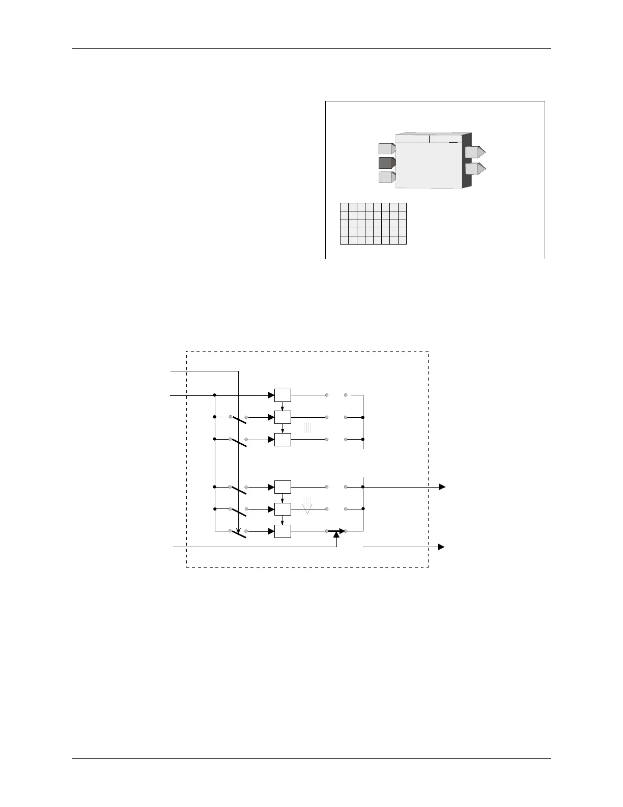
3.2.34 DTM_ - Dead Time Table
DTM_ function blocks provide shift registers to hold the
analog input signal A for a period of time and shift it from
register to register to provide an overall delay between
input and output as configured in parameter DEADTIME.
Input AT can be used to adapt the DEADTIME to an
external signal. The actual shift register used as the block
output will equal the whole value of input AT (e.g. 0.184 =
register 0, 1.897 = register 1).
Output MA will provide the moving average of register 0
to the output register divided by the number of registers
[e.g. output register = 50, MA = (R0+R1+R2+......+R50)/51].
Input E asserted high (1) will enable the operation of the DTM block. When this input is not configured, it will be
set high. A low (0) input will cause all registers and the outputs to equal the input A.
POWER UP - During a warm or cold start, all outputs will be initialized at 0 and all registers will be initialized to
the value of the input on the first scan.
BLOCK DIAGRAM
A
O1
.
.
.
.
.
.
.
.
.
.
.
.
.
.
.
.
SHIFT REGISTERS
E
AT
A
daptive
T
ime
A
nalog Input
E
nable
O
utput
1
n
n-1
n-2
n-48
n-49
n-50
Register 0
Register 1
Register 50
MA
M
oving
A
verage
.
A
nalog Input
DEAD TIME
E
T
D
E
I
N
U
E
DEAD TIME
(S)
........ 0.0 to 10000 min. (0.0)
INPUT E
(H)
.......
loop tag.block tag.output (null)
O1
O
utput
1
DEAD TIME
DTM_
ESN =
000
I
M
D
T
P
A
ESN
E
xec.
S
eq.
N
o.
(H)
.............. 001 to 250
E
nable
E
A
daptive
T
ime
AT
MA
M
oving
A
verage
A
I
N
U
AT
P
I
N
U
TT
P
INPUT A
(H)
.......
loop tag.block tag.output (null)
INPUT AT
(H)
.....
loop tag.block tag.output (null)
A