Function Blocks UM353-1B
April 2012
3-10
3.2.4 AG3 - AGA 3 Orifice Metering of Natural Gas
AG3 function blocks can be used on a one per loop basis. This
block uses the AGA 3 (American Gas Association Report #3)
calculation to accurately measure the flow of natural gas using
an orifice meter with flanged taps. The basic equations
calculated by this block, in accordance with AGA Report No. 3,
Orifice Metering of Natural Gas, Part 3, November 1992 (AGA
Catalog No. XQ9210), are:
Q
b
= C' √ P
f1
h
w
C' = F
n
(F
c
+F
sl
)Y
1
F
pb
F
tb
F
tf
F
gr
F
pv
where:
Q
b
= volume flow rate at base conditions
C' = composite orifice flow factor
P
f1
= absolute flowing pressure(upstream tap)
h
w
= orifice differential pressure
F
n
= numeric conversion factor
F
c
= orifice calculation factor
F
sl
= orifice slope factor
Y
1
= expansion factor (upstream tap)
F
pb
= base pressure factor
F
tb
= base temperature factor
F
tf
= flowing temperature factor
F
gr
= real gas relative density factor
F
pv
= supercompressibility factor
Output Q
b
is updated every scan cycle. Output C' is updated continuously for temperature effects and periodically
for other effects. The following conditions are considered in the calculations:
• Standard Conditions are:
P
s
= 14.73 psia, T
s
= 60°F, Z
sair
= 0.999590.
• Nominal pipe size is 2" or larger, Beta is 0.1 - 0.75, and Re (Reynolds Number) is 4000 or larger.
•
Y (expansion factor) and absolute flowing pressure P
f
are referenced to upstream tap (i.e. Y
1
& P
f1
).
• h
w
is in inches H
2
0 and P
f
is in psia. 0 < [h
w
/(27.707*P
f
)] <= 0.2.
The following parameters are configuration entries:
d
r
= orifice plate bore diameter in inches at a reference temperature of 68°F
D
r
= meter tube internal diameter in inches at a reference temperature of 68°F
P
b
= base pressure (psia)
T
b
= base temperature (°F)
The following are analog inputs to the AGA 3 function block:
h
w
= orifice differential pressure (in H
2
O)
P
f
= flowing pressure at upstream tap - P
f1
(psia)
T
f
= flowing temperature (°F)
G
r
= real gas relative density (specific gravity)
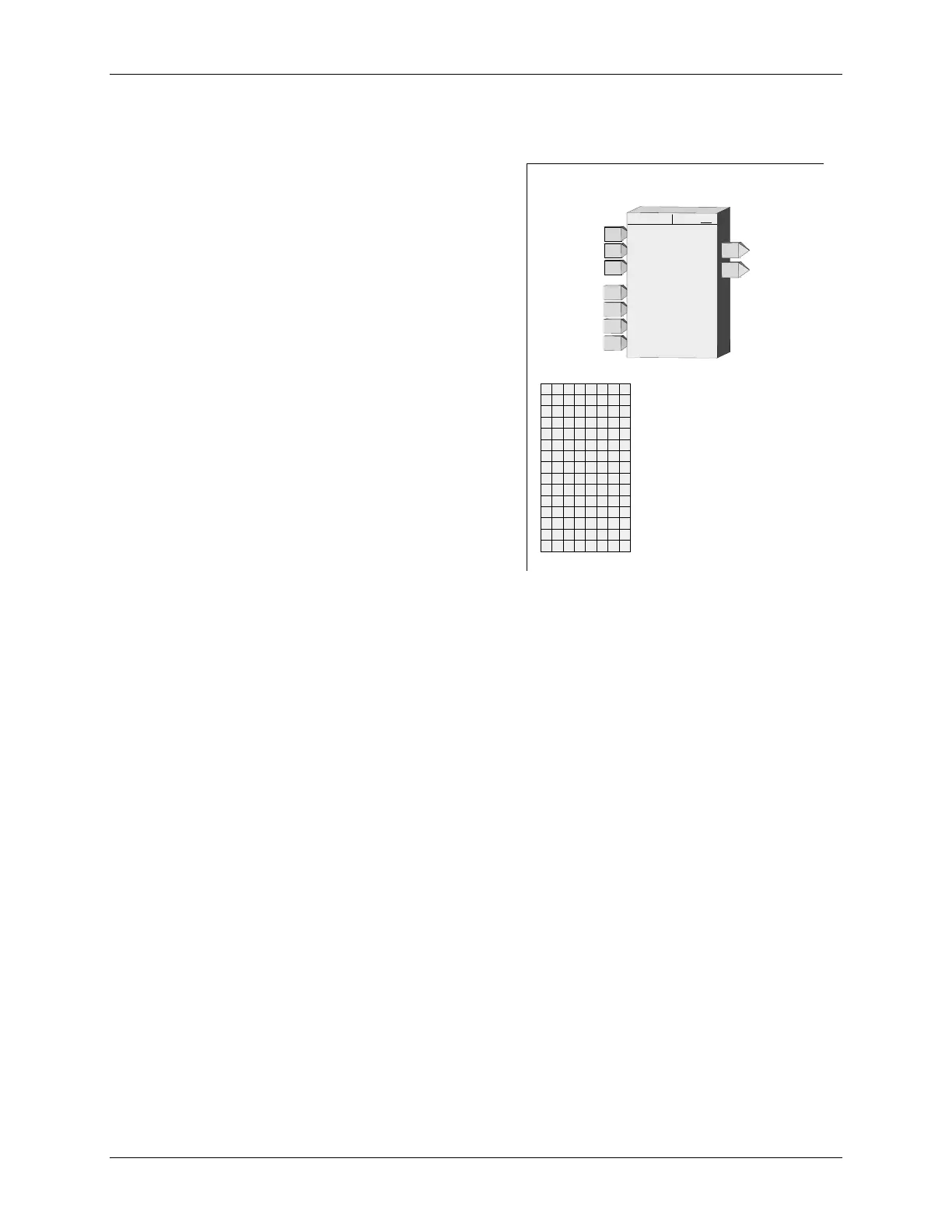
Input
hw
AGA 3
Qb
Output
Qb
AGA 3
AG3 ESN =
000
hw
E
xec.
S
eq.
N
o. ..................... 000 to 250 (000)
Input
Pf
Pf
INPUT Zb
.............
loop tag.block tag.output
(
null
)
Input
Tf
Tf
Input
Gr
Gr
Input
Zs
Zs
Input
Zf
Zf
Input
Zb
Zb
C'
Output
C'
TUP
N
I
d
r
r
D
hw
TU
P
N
I
P
f
TUP
N
I
TUP
N
I
TU
P
N
I
TUP
N
I
T
U
P
N
I
P
b
f
T
Tb
G
r
Z
f
s
Z
Z
b
S
E
N
INPUT Zf
.............
loop tag.block tag.output
(
null
)
INPUT Zs
.............
loop tag.block tag.output
(
null
)
INPUT Gr
.............
loop tag.block tag.output
(
null
)
INPUT Tf
..............
loop tag.block tag.output
(
null
)
INPUT Pf
..............
loop tag.block tag.output
(
null
)
INPUT hw
............
loop tag.block tag.output
(
null
)
D
iameter
r
ef.
for tube (inches) ................... Real
(0.0)
d
iameter
r
ef.
for plate (inches) .................... Real
(0.0)
b
ase
P
ressure (psia)
.............................. Real
(14.73)
b
ase
T
emperature (deg F)
................... Real
(60.0)
k
Specific Heat Ratio (
k
)
.......................... Real
(1.30)
um
Viscosity x 10
-6
lbm/ft-sec (
mu
)
........ Real
(6.90)
PLATE
PLATE
Material
.................... SS=0,Monel=1,CS=2
(SS)

 Loading...