Installation UM353-1B
April 2012
7-20
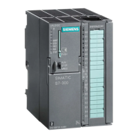
7.4.11 Wiring to a Siemens SIREC D Recorder
Figure 7-19 shows the wiring needed to connect a SIREC D analog input to a Model 353 analog input. As shown, a
1-5 Vdc transmitter input to the Model 353 is also routed the recorder’s Analog Input 1.
5
+
_
Common Ground Bus
Earth
Ground
SITRANS P
DSIII, 2-Wire
Transmitter,
4-20 mA Output
MG00502d
18*
1-5 Vdc
26 Vdc
H
N
External
Power
120/240 Vac
25W
47-63 Hz
Hot
Neutral
Earth Ground
Model 353A
Controller Terminals
G
2
1
SIREC D
Recorder Terminals
Channel 1
Analog Input
See Note 2
Notes:
1. See Table 7-1 for Model 353 AIN2, 3, and 4 terminals.
2. Refer to the Siemens SIREC D manual for details and other analog inputs.
5
4
+
_
SITRANS P
DSIII, 2-Wire
Transmitter,
4-20 mA Output
Power Supply
+
_
Channel 2
Analog Input,
See Note 2
AIN1
20
Station
Common
250
Ω
Ω
10
*Or any station common terminal
6
Figure 7-19 Model 353 to Siemens SIREC D Recorder Analog Input Wiring
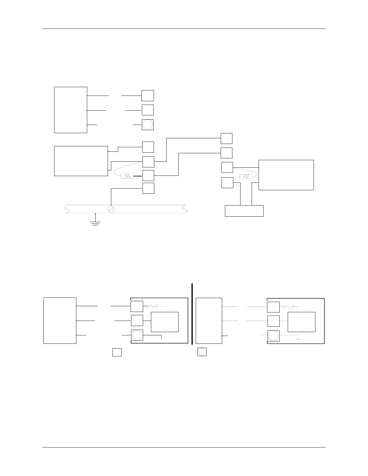
7.4.12 Power Wiring
Basic connections for AC and DC power input are shown in Figure 7-20. Wiring guidelines are given in Section
7.4.1.
H
Model 353D
Rear Terminals
X03106S0
N
External
Power
120/240 Vac
25W
47-63 Hz
Hot
Neutral
Earth Ground
External
Power
24 Vdc
25W
(+)
(-)
Earth Ground
Model 353A
Rear Terminals
H
N
DC To DC
Power Supply
on
MPU Board
AC To DC
Power Supply
on
MPU Board
Controller Circuitry
Controller Circuitry
H
=Terminal on rear of case.
G
G
= Green screw at top center of rear terminal area.
G
Figure 7-20 Controller Power Wiring
Power input to a Siemens should be routed through a clearly labeled circuit breaker, fuse or on-off switch that is
located near the controller and is accessible by the operator. The protective device should be located in a non-
explosive atmosphere unless suitable for use in an explosive atmosphere. This type of wiring is shown in Figure 7-
21. It will permit removal of controller power without affecting the on-line status of adjacent controllers.

 Loading...