EasyManua.ls Logo

Siemens 353 User Manual

Siemens 353
246 pages
To Next Page IconTo Next Page
To Previous Page IconTo Previous Page
Page #77 background imageLoading...
Page #77 background image
UM353-1B Function Blocks
April 2012
3-47
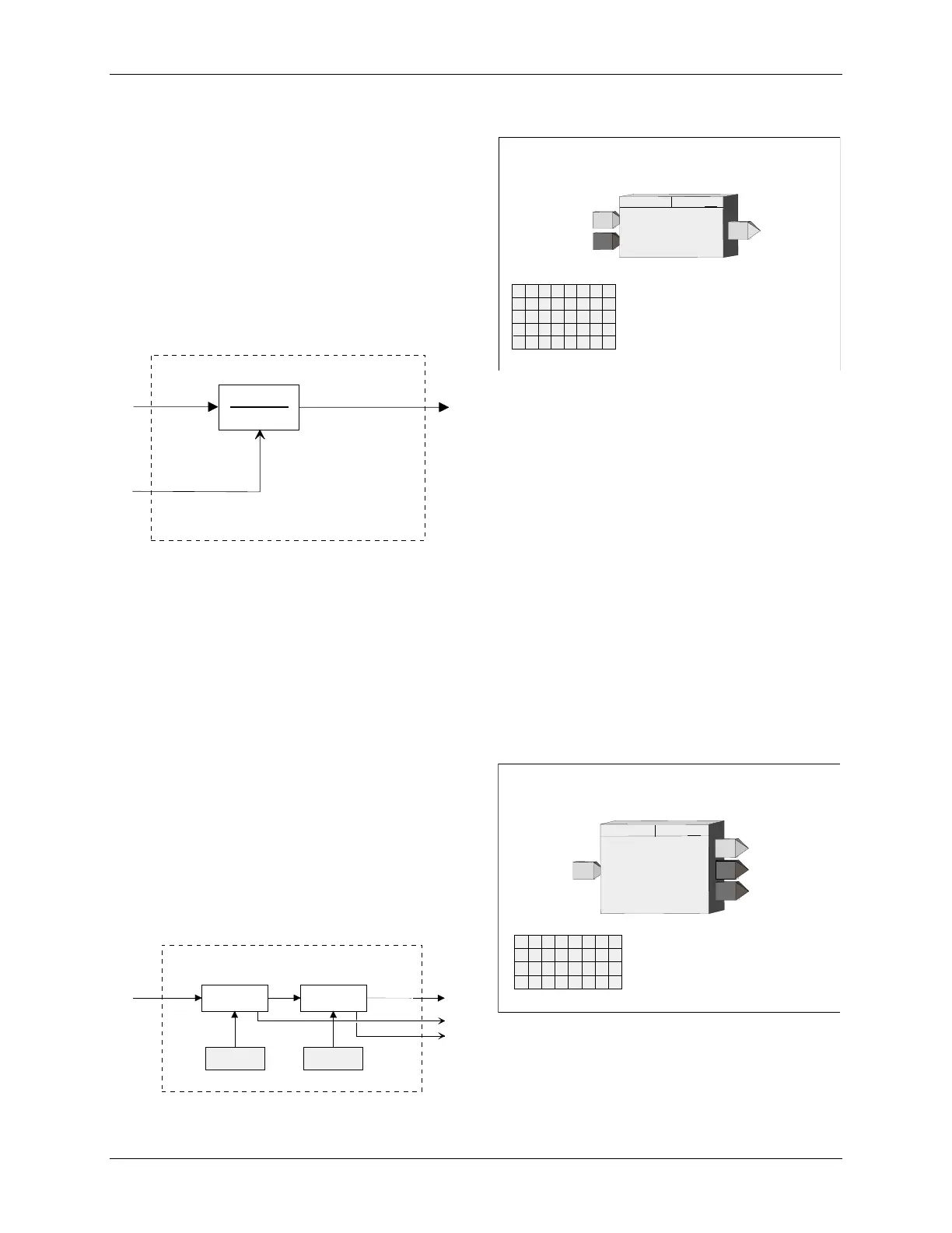
3.2.45 LL_ - Lead/Lag
LL_ function blocks provide both lead and lag functions.
The block can function as lag only by setting the TLEAD
time to 0.0. The lag function is always active and has a
minimum setting of 0.01 minutes.
Input E asserted high (1) will enable the Lead/Lag
function. When asserted low (0), the Lead/Lag function
will be bypassed and the output will be set equal to the
input. If input E is not configured, the block will be
enabled.
BLOCK DIAGRAM
O1
E
A
t
Lead
+ 1
t
Lag
+ 1
E
nable
A
nalog Input
O
utput
1
.
POWER UP - During a warm or cold start, the dynamic elements and the output will be initialized to the value of
the current input on the first scan.
3.2.46 LMT_ - Limit
LMT_ function blocks are used to limit a real signal.
Input A will normally pass through the function block to
the output O1. If the input exceeds one of the limits, the
block will output the limit value.
If the HI LIMIT is set lower than the LO LIMIT, the block
will output the high limit value. The output statuses will
be high (1) when the block is in a limit condition.
BL
OC
K DIA
G
RAM
HI SELECTOR
LO SELECTOR
HI LIMIT
A
O1
LO LIMIT
HS
LS
O
utput
1
H
igh limit
S
tatus
L
ow limit
S
tatus
.
.
A
nalog Input
LEAD/LAG
G
T
T
L
E
T
ime -
LAG
(min)
(S)
....... 0.01 - 10000.0 (0.10)
T
ime -
LEAD
(min)
(S)
..... 0.00 - 10000.0 (0.00)
O1
O
utput
1
LEAD/LAG
LL_
ESN =
000
A
L
A
E
E
nable
I
I
N
N
P
P
U
U
T
T
A
E
INPUT E
(H)
...........
loop tag.block tag.output (null
)
ESN
E
xec.
S
eq.
N
o.
(H)
................. 001 to 250
A
D
INPUT A
(H)
..........
loop tag.block tag.output (null)
Input
A
LIMIT
TI
H
I
O
L
I
N
U
A
HI
gh
LIMIT
(S)
........................... Real (100.00)
LO
w
LIMIT
(S)
........................... Real (0.00)
INPUT A
(H)
.....
loop tag.block tag.output (null)
HS
H
igh
S
tatus
LIMIT
LMT_
ESN =
000
I
M
L
T
P
A
L
I
M
I
T
ESN
E
xec.
S
eq.
N
o.
(H)
............ 001 to 250
O1
O
utput
1
L
ow
S
tatus
LS

Table of Contents

Question and Answer IconNeed help?

Do you have a question about the Siemens 353 and is the answer not in the manual?

Siemens 353 Specifications

General IconGeneral
CPUCPU 353
Inputs16 digital inputs, 24 V DC
Outputs16 digital outputs, 24 V DC, 0.5 A
CommunicationMPI
Power Supply24 V DC

Summary

PREFACE

General Warnings and Cautions

Highlights hazards like high voltages and the need for qualified personnel and safety adherence.

1.0 INTRODUCTION

1.2 FUNCTION BLOCKS

Explains the controller's software architecture based on reusable function blocks and their types.

2.0 CONFIGURATION OVERVIEW

2.5 CONFIGURATION PROCEDURE

Outlines the steps for configuring the controller, both locally via faceplate and remotely via PC.

3.0 FUNCTION BLOCKS

3.2 I/O AND LOOP FUNCTION BLOCKS

Describes input/output and loop function blocks, listed alphabetically.

4.0 FACTORY CONFIGURED OPTIONS

4.1 FCO101 - Single Loop Controller w/ Tracking Setpoint

Describes FCO101, a single loop controller configured in Loop01, providing setpoint tracking.

6.0 DATA MAPPING

7.0 INSTALLATION

7.4 ELECTRICAL INSTALLATION

Contains details for wiring the Siemens 353, including general wiring guidelines and specific I/O wiring.

8.0 LOCAL FACEPLATE OPERATION

8.3 AUTOTUNE PROCEDURE

Outlines the procedure for initiating and performing the autotune function for controller tuning via the TUNE pushbutton.

9.0 CONTROLLER AND SYSTEM TEST

9.1 CONTROLLER CONFIGURATION AND TEST

Provides steps to configure and test the controller, including connections, power, and initial setup.

10.0 MAINTENANCE

10.3 TROUBLESHOOTING

Guides users on troubleshooting controller issues using error codes, power-up sequences, and assembly substitution.

10.4 ERROR CODES

Describes off-line and on-line error codes, status codes, and their corresponding corrective actions.

10.5 ASSEMBLY REPLACEMENT

Outlines procedures for replacing controller assemblies, including MPU Controller Board, I/O Expander Board, and Display Assembly.

11.0 CALIBRATION

13.0 MODEL DESIGNATION AND SPECIFICATIONS

Related product manuals