Function Blocks UM353-1B
April 2012
3-4
3.1.3 STATN - Station Parameters
The STATN function block enables entry of station
identification and other station related information.
When the station is networked using Modbus, the
address is used by higher level devices to obtain
information from the station. Modbus can range from
1-250 but normally 1-32 is used to correspond to the
total number of devices that can be installed on a single
network.
Once the address has been assigned and higher level
devices have been configured to access information
from the station, changing the address can require
reconfiguration of the higher level device. There may
also be higher level devices that will query and assign
addressing information based on the station tag name.
In this case, a tag name change will also require
reconfiguration of higher level devices. Therefore, it is
important not to change the station identification
without being aware of system consequences.
There are two timers used during power up
initialization: WARM TIM and COLD TIM. The
station takes approximately 15 seconds to perform
power up initialization before the power up time is
evaluated. Set a timer to a value of 20 seconds or
greater, for the timer to be effective. A timer setting of
0 will be considered as infinite (e.g. to always power
up hot, set the warm timer to 0). A setting of 1 through
19 will default to 20. Configurations downloaded with
a warm time setting less than the power up time will be set to the power up time. When the station powers up after a
loss of power but prior to the expiration of the warm timer, the station will execute a Hot Start. If the station powers
up after the warm timer expiration but prior to expiration of the cold timer, the station will execute a warm start. In
all other cases, the station will execute a cold start.
When using Modbus Network communications, the WATCHDOG timer can be set to a value other than 0 to cause
a high WD output from the loop operator display function block when the station does not receive a read command
of the Active Station Event coil (00001) within the timer period. A value of 0 disables the watchdog. A Modbus
communications DELAY time can be entered for both the Display Assembly configuration port and Modbus
terminals NCA/NCB (front and rear ports respectively). This may be necessary when the station responds too
quickly for the modem. Modbus masters may handle IEEE floating point numbers in a different word order. The
IEEE REV parameter allows matching the station to the Modbus master in use.
The CONFG LO (Configuration Lockout) parameter and PARAM LO (Parameter Write Lockout) parameter
provide a method for locking out configuration transfers and parameter read/writes from a PC over a Modbus or
Ethernet network. A 0 allows writes, a 1, 2, or 3 prevents writes. (There is no difference in operation in selecting a
1, 2, or 3.)
The 8-digit SERIAL # of the station is stored in memory and can be viewed when this parameter is displayed. If
only seven digits are seen, assume a leading zero.
BAUD rate parameters set the Modbus port characteristics; see Table 3-2. The network Modbus port at terminals
NCA and NCB, the rear port, is RS485 and uses the assigned station address. The configuration port, the front port,
is RS232 and uses an address of 1.
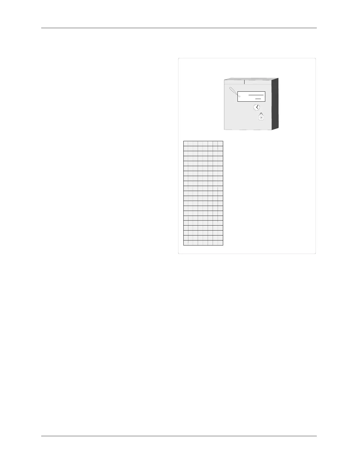
STATION PARAMETERS
E
Station
ADDRESS
(H)
.................... 0 - 250 (0)
STATION PARAMETERS
STATN
S
S
DD
G
A
T
Station
TAG
(S)
.................. 12 Char ASCII (PAC 353)
ADDRESS: 24
TAG:
UNIT NO. 3
AR
IDENTIFICATION TAG
STATION TIMERS
WA R M T I M
WARM TIM
er (sec)
(S)
............. 0 - 999999 (20)
COLD TIM
er (sec)
(S)
.............. 0 - 999999 (100)
COLD T I M
WA T C D O GH
WATCHDOG
timer (sec)
(S)
........ 0 - 1000 (0)
12
6
3
9
CONF LO
MPAR O
G
L
CONF
i
G
uration
L
ock
O
ut
(S)
.......... 0/1/2/3 (0)
(1)
PARAM
eter
L
ock
O
ut
(S)
............... 0/1/2/3 (0)
(1)
A
PC WRITE LOCKOUT
SER I AL #
SERIAL #
(R)
...................... 0 to 99999999 (xxxxxxxx)
DRP B UA
DFP B UA
SFP TR
R
ear
P
ort
BAUD
rate
(S)
.......... (Table 3-2) (5)
F
ront
P
ort
BAUD
rate
(S)
......... (Table 3-2) (6)
F
P
RTS
/CTS
handshaking
(S)
....... (Table 3-2) (1)
BAT
tery
OK
(R)
..............................
NO/YES
HW PRES
H
ard
W
are
PRES
ent
(R)
.............(Table 3-3)
CT BASE
C
ycle
T
ime
BASE
msec
(R)
..........
20 to 2000
CT B ASI
C
ycle
T
ime
BIAS
msec (H) ................ 0 to 1000
(0)
CM
VM
AVA I L
AVA I L
C
onstant
M
em
AVAIL
able
bytes
(R)..
varies w/ software rev
V
olitile
M
em
AVAIL
able
bytes
(R).....
varies w/ software rev
KOTAB
IEEE REV
IEEE
Floating Point
REV
erse
(S)
. NO/YES (YES)
RP DEL AY
R
ear
P
ort
DELAY
(S)
.......... 0 - 1000 msec (0)
FP DELAY
F
ront
P
ort
DELAY
(S)
......... 0 - 1000 msec (0)
CONFG TO
CONF
i
G
uration
T
ime
O
ut
(H)
.........
NO/YES (YES)
(1) - 0-No Lock Out, Writes Allowed; 1, 2, or 3-Lock Out Enabled, Writes Not Allowed [r2 B-Level]

 Loading...