UM353-1B Function Blocks
April 2012
3-17
3.2.9 AINU_ - Analog Inputs, Universal
AINU_ function blocks are available on the optional I/O
Expander Board. These function blocks convert sensor inputs
such as T/C (thermocouple), RTD (resistance temperature
detector), millivolt, ohm, and slidewire sources into block
outputs. Current inputs (i.e. 4-20 mA) are accommodated by
using the WMV type and connecting a 3.75Ω resistor across
the input. An output bias can be used to nullify any known
offset in the sensor circuit and a digital filter (time constant)
is included, to dampen process noise. Output QS indicates the
quality status of the output signal O1 and will go high (1)
when the output is of bad quality. Bad quality indicates an
A/D conversion failure or an open circuit T/C.
The scaling function is used to establish an output range, in
engineering units, for the selected sensor range (e.g. 0-10 mv
or 50.0-150.0 amperes). Direct Temperature Measurements
(i.e. T/C and RTD) bypass sensor and range scaling and the
block output units are selected from Table 3-7. When
selected, the proper read only ASCII characters
corresponding to the type units selected will automatically be
placed in the ENG UNITS parameter. When OHMs or MVs
are selected, the ENG UNITS parameter can be configured to correspond to the process engineering units. The
default SEN MIN and MIN SCALE are set to the minimum operating value and SEN MAX and MAX SCALE are
set to the maximum operating value. SEN MIN and SEN MAX always indicate the sensor range limits in degrees
C. However, it is important to enter the actual intended operating range in the MINSCALE, MAXSCALE, and
DPP parameters so that other function blocks, such as the controller, operator faceplate, and workstation interface,
can point to this block for range and display informationBlock names (IDs). Input terminations (terminal numbers)
are listed in Section 7.4 Electrical Installation.
All input types are factory calibrated and do not require field calibration. However, for those cases where outputs
must be adjusted to meet a local standard, a field calibration feature is available to override the factory calibration
for the input type selected. The factory calibration is retained so that the input can be returned to the factory
calibration at any time by storing ‘FAC’ in the calibration selection. Table 3-8 provides the input values that are
used to perform a field calibration. A verify mode is available during calibration to view the sensor input over the
full range. The signal that is viewed, in the calibration verify mode, is in the basic units of measure (e.g. °C for
temperature, mv for millivolts) and is not affected by the temperature units conversion, digital filter, scaling, or the
output bias adjustment. The full block output with these parameters applied can be viewed in the VIEW mode
within loop configuration. During a hot, a warm or a cold start, the function block will temporarily by-pass the
digital filter to enable the output to initialize at the actual hardware input signal. Note that the field
calibration is
erased when the SENsor TYPE is changed.
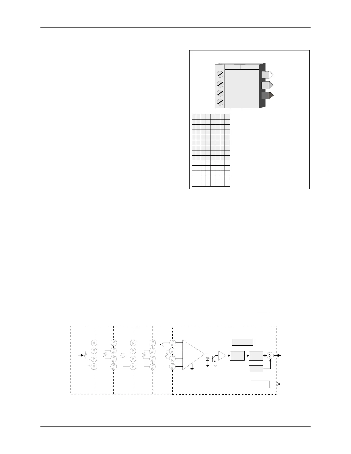
BLOCK DIAGRAM
O1
Digital
Filter
QS
Quality Test
Universal
Converter
D/A
T/C
RJ
T/C
RTDMV
OHM
SLIDE WIRE
RTD
MV
+
_
OHM
b -----
a -----
d -----
c -----
Range
Scaling
Bias
+
+
ENG UNITS
_
+
.
.
Converter
Models 353
and 354 only
Models 353
and 354 only
AINU_a
AINU_b
ANALOG INPUT- UNIVERSAL_
N
ET
E
I
N
F
SG
T
L
C
C
ZERO
FLL
V
EIW
ENGineering UNITS (H)
.... Input Types Table (1)
DIG
ital
FILT
er
(S)
............... 0 to 180 sec (0 sec)
CAL TYPE (C)
. (
Sen Min/Max Table
_ FLD/FAC
)
(FAC)
ZERO
field calibration
(C)
.
Cal. Input Values Table
FULL
scale field cal
(C)
.....
Cal. Input Values Table
VIEW
input - verify cal
(C)
.............. Real
O1
O
utput
1
ANALOG INPUT
U
AINU_
P
Y
DIG
C
A
L
LA
A
L
S
I
QS
Q
uality
S
tatus
UNIVERSAL
AINU_c
AINU_d
T/C, RTD, MV, OHMS
NU
SEN
sor
TYPE
(H)
..
Cal. Input Values Table
(15)
CA L T
Y
PE
SLIDEWIRE
E
OUT
put
BIAS
(S)
............................ Real (0.0)
OU T
BI
A
S
MIN
imum
SCALE
(H)
...
Sen Min/Max Table
(-185)
MINSCA
L
E
MXA
S
CAL
E
MAX
imum
SCALE
(H)
..
Sen Min/Max Table
(1100)
S
S
E
E
N
N
MIN
M
AX
SEN
sor
MAX
imum
(H)
...
Sen Min/Max Table
(75)
SEN
sor
MIN
imum
(H)
. ..
Sen Min/Max Table
(15)
T
PPD
D
ecimal
P
t.
P
osition (preferred)
(S)
.... . 0.0.0.0. 0.0 0.00
OR
O
utput
R
ange
(Rev. 3)
DTMUN S
I
T
D
ir.
T
emp.
M
eas.
UNITS
(S) ..
Input Types Table (1)

 Loading...