Function Blocks UM353-1B
April 2012
3-42
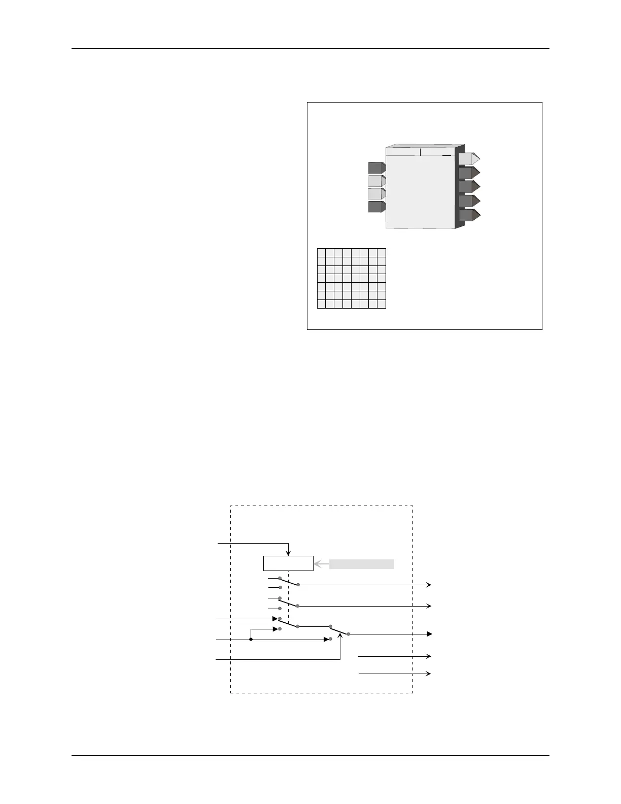
3.2.37 E/I - External/Internal Transfer Switch
E/I function blocks can be used on a one per loop
basis to select an analog signal, connected to input E
(External) or input I (Internal), as a setpoint for the
loop controller.
The position of the E/I switch can be changed on each
positive transition of input ST and will normally be
connected to the PS output of pushbutton block
PB2SW, configured for momentary action. The SE
output will normally be connected to the MD input of
pushbutton block PB2SW. E/I switch position will be
shown on the operator faceplate by a lighted LED:
green for E, red for I.
The E/I switch position can also be changed by an
operator HMI command over the Modbus RS485 or
Modbus/TCP Ethernet networks.
When PU LAST is set to YES, the E/I switch will
power up in the last position during a hot or a warm
start. During a cold start, it will power up in the position set by the POWER UP parameter. If PU LAST is set to
NO, the E/I switch will power up in the last position during a hot start, but during a warm or cold start will power
up in the position set by the POWER UP parameter.
The IO (Internal Override) input enables a HI (1) input to temporarily select the Internal Input as the function block
output O1. This input does not affect the position of the E/I switch.
Outputs SE and SI indicate the actual position of the E/I switch. SE is HI (1) when in the E position and LO (0)
when in the I position. SI is HI when in the I position and LO when in the E position. Outputs IS and ES indicate
the actual source of the block output. IS is HI when O1 is the Internal input and is LO when O1 is the External
input. ES is HI when O1 is the External input and is LO when O1 is the Internal input.
E
xternal Input
E/I TRANSFER SWITCH
E
R
P
O
I
N
U
E
POWER UP
position
(S)
......................... E/I (I)
INPUT E
(H)
...............
loop tag.block tag.output (null)
O1
O
utput
1
TRANSFER SWITCH
E/I
ESN = 000
TP
E
I
IO
E/I
I
nternal Input
I
nternal
O
verride
IS
E
xternal
S
tatus
I
N
N
P
P
U
U
T
T
I
I
INPUT I
(H)
.................
loop tag.block tag.output (null)
INPUT IO
(H)
..............
loop tag.block tag.output (null)
EN
E
xec.
S
eq.
N
o.
(H)
...................... 001 to 250
W
U
P
ES
I
nternal
S
tatus
SE
SI
S
witch position
E
O
S
I
P
ower
U
p
LAST
(S)
....................... NO/YES (YES)
P
U
LAS
T
S
witch position
I
ST
S
witch
T
ransfer
NP
U
T
S
T
I
INPUT ST
(H)
.............
loop tag.block tag.output (null)
BLOCK DIAGRAM
E
I
IO
SI
SE
O1
O
utput
1
I
nternal
O
verride
E
xternal
S
tatus
I
nternal
S
tatus
ES
IS
S
witch position
E
E
xternal
I
nternal
1
1
0
0
EI Transfer Switch
ST
S
witch
T
ransfer
Switch Control
S
witch position
I
E/I
Network Command

 Loading...