EasyManua.ls Logo

Siemens 353 User Manual

Siemens 353
246 pages
To Next Page IconTo Next Page
To Previous Page IconTo Previous Page
Page #63 background imageLoading...
Page #63 background image
UM353-1B Function Blocks
April 2012
3-33
1. oncE will write once to the START CL (Modbus Starting Coil. The controller will write when any block input
value changes state.
2. P2P will update at the controller peer to peer rate set in the ETHERNET block.
3. Ct will update at the cycle time of the controller.
The Ct option is normally only used when writing time critical changes. Input T can be used to trigger a write. This
would be used in cases where the oncE option has been selected, input values do not change, and there may be a
concern that the receiving device has lost the values.
Output QS indicates the quality of the write operation and will go high (1) when the write is not completed
successfully. This is normally associated with failure of the destination device to receive data due to a
communication failure or a misconfiguration of the device.
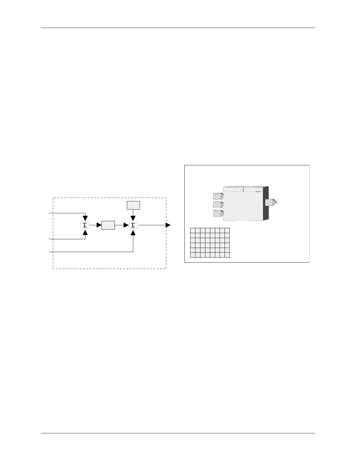
3.2.26 DAM_ - Deviation Amplifier
DAM_ function blocks compute the difference between
inputs A and B, amplify the difference signal, and sum the
resultant with an internal BIAS and an external signal at
input C. Unused inputs are set to 0.0.
BLOCK DIAGRAM
A
O
utput
1
-
GAIN
+
O1
BIAS
Input
A
Input
B
Input
C
B
C
+
+
+
O1 = GAIN x (A - B) + BIAS + C
.
.
Input
A
DEVIATION AMPLIFIER
NG
I
N
U
C
GAIN
(S)
.................................... Real (1.0)
BIAS
(S)
..................................... Real (0.0)
INPUT C
(H)
.....
loop tag.block tag.output (null)
O1`
O
utput
1
DEVIATION
DAM_
ESN =
000
I
A
T
P
A
B
A
I
S
ESN
E
xec.
S
eq.
N
o.
(H)
............ 001 to 250
AMPLIFIER
Input
B
B
Input
C
C
I
N
U
AT
P
I
N
U
BT
P
INPUT B
(H)
.....
loop tag.block tag.output (null)
INPUT A
(H)
.....
loop tag.block tag.output (null)

Table of Contents

Question and Answer IconNeed help?

Do you have a question about the Siemens 353 and is the answer not in the manual?

Siemens 353 Specifications

General IconGeneral
CPUCPU 353
Inputs16 digital inputs, 24 V DC
Outputs16 digital outputs, 24 V DC, 0.5 A
CommunicationMPI
Power Supply24 V DC

Summary

PREFACE

General Warnings and Cautions

Highlights hazards like high voltages and the need for qualified personnel and safety adherence.

1.0 INTRODUCTION

1.2 FUNCTION BLOCKS

Explains the controller's software architecture based on reusable function blocks and their types.

2.0 CONFIGURATION OVERVIEW

2.5 CONFIGURATION PROCEDURE

Outlines the steps for configuring the controller, both locally via faceplate and remotely via PC.

3.0 FUNCTION BLOCKS

3.2 I/O AND LOOP FUNCTION BLOCKS

Describes input/output and loop function blocks, listed alphabetically.

4.0 FACTORY CONFIGURED OPTIONS

4.1 FCO101 - Single Loop Controller w/ Tracking Setpoint

Describes FCO101, a single loop controller configured in Loop01, providing setpoint tracking.

6.0 DATA MAPPING

7.0 INSTALLATION

7.4 ELECTRICAL INSTALLATION

Contains details for wiring the Siemens 353, including general wiring guidelines and specific I/O wiring.

8.0 LOCAL FACEPLATE OPERATION

8.3 AUTOTUNE PROCEDURE

Outlines the procedure for initiating and performing the autotune function for controller tuning via the TUNE pushbutton.

9.0 CONTROLLER AND SYSTEM TEST

9.1 CONTROLLER CONFIGURATION AND TEST

Provides steps to configure and test the controller, including connections, power, and initial setup.

10.0 MAINTENANCE

10.3 TROUBLESHOOTING

Guides users on troubleshooting controller issues using error codes, power-up sequences, and assembly substitution.

10.4 ERROR CODES

Describes off-line and on-line error codes, status codes, and their corresponding corrective actions.

10.5 ASSEMBLY REPLACEMENT

Outlines procedures for replacing controller assemblies, including MPU Controller Board, I/O Expander Board, and Display Assembly.

11.0 CALIBRATION

13.0 MODEL DESIGNATION AND SPECIFICATIONS

Related product manuals