Function Blocks UM353-1B
April 2012
3-36
3.2.29 DINU_- Digital Inputs, Universal
DINU_ blocks have multi-function capability:
• sensing a discrete input and providing a high (1) or low
(0) output representing the state of the input
• totalizing and scaling the count of input pulses
• converting the rate of input pulses to a scaled analog
frequency output
Two DINU_ blocks are available on the I/O expander board.
The fixed names (IDs) of these blocks and their terminal
designations are listed in Section 7.4 Electrical Installation.
Output CT represents the scaled (actual count x K) total of
input pulses that occurred since the last reset. This output is a
real number and can be used in a number of applications,
such as a direct count input to the BAT batch totalizer
function block or in math operations, such as computing the
difference between counts in a ratio trim circuit.
Output IS is the current state of the input at the time the
block is executed at the start of each controller scan cycle. It
will be low (0) when the input is low and high (1) when the
input is high.
Output SF is a scaled frequency (using the FREQ MIN and MAX parameters) that can represent flow rate, speed, or
other transmitter variable that has a frequency signal. When the FREQ MAX parameter is set to 25 or less, a 20
msec contact debounce is used. When contact debounce is used, a pulse input must remain on for 20 msec to be
recognized as a valid pulse. Output SF is linear with frequency and can be characterized using the CHR function
block if necessary. An engineering range and units are assigned to this signal using the MINSCALE, MAXSCALE,
DPP, and ENGUNITS parameters. They are available to other blocks using the OR output connection.
Input R resets output CT to 0.0. Input D controls the direction of the count. When direction input D is low (0), the
count will move backwards, including negative values. The direction input feature enables the use of count down
counters and it allows duplication of functions performed by previous computer pulse interfaces having a
Pulse/Direction format. Input TC asserted high (1) will force the scaled count to track an external signal. This can
be used in applications where the CT output is being used to set a value (e.g. setpoint) that can be changed from
another source.
The quality status output QS indicates the
quality of the block outputs and is high (1)
when outputs CT, IS, or SF are of bad
quality. Bad quality indicates a failure in the
hardware conversion circuit.
POWER UP - With PU LAST set to YES, the
CT output will power up at the last value
during a hot or warm start. If set to NO,
during a warm or a cold start, it will be set to
0.0. The digital filter will be temporarily by-
passed during a hot, a warm or a cold start.
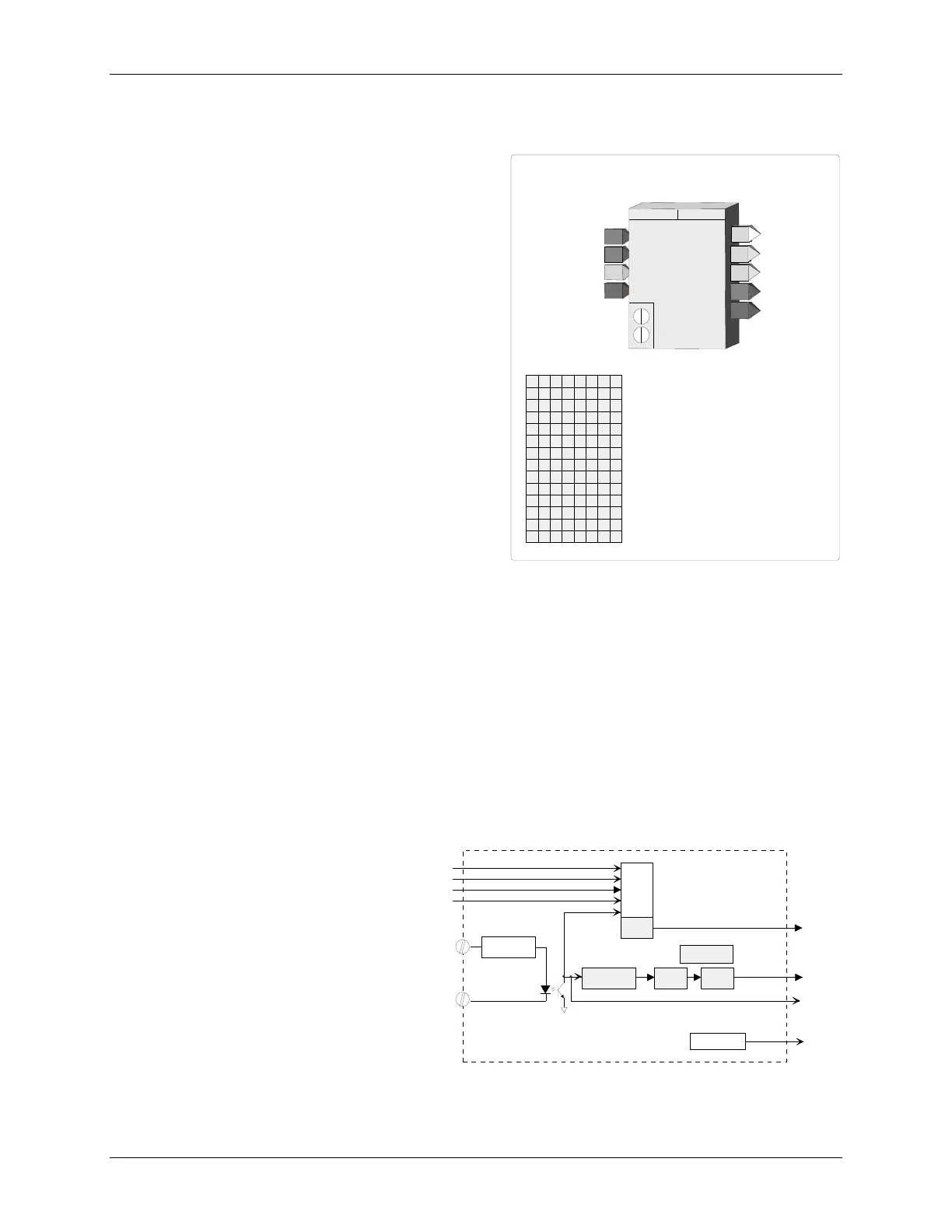
BLOCK DIAGRAM
CT
Count
QS
Quality Test
DIU_+
DIU_-
R
D
TV
TC
R
eset
D
irection
T
rack
V
ariable
T
rack
C
ommand
C
ount
T
otal
IS
P/A Converter
Scaling
SF
S
caled
F
req.
ENG UNITS
Digital
Filter
K
.
.
Current Limit < 7 mA
R
eset
DIGITAL INPUT - UNIVERSAL
N
FREQ
uency
MIN
imum Hz
(H)
................ Real
(0)
MIN
imum
SCALE
(H)
............................. Real
(0.0)
CT
C
ount
T
otal
UNIVERSAL
DINU_
I
R
D
TV
TC
DIGITAL INPUT
D
irection
T
rack
V
ariable
T
rack
C
ommand
IS
I
nput
S
tate
INPUT
EL
E
I
I
N
N
P
P
U
U
T
T
R
D
INPUT R
(H)
..................
loop tag.block tag.output (null)
V
M
AX
A
C
F
Z
ero
D
rop
O
ut (Engineering Units)
(H)
.. Real
(0)
R
T
SF
S
caled
F
req.
M
Q
E
F
R
Q
NIM
AXM
S
ELACS
Z
D
O
CTINPUT
FREQ
uency
MAX
imum Hz
(H)
............... Real
(1000)
MAX
imum
SCALE
(H)
............................ Real
(100.0)
INPUT D
(H)
..................
loop tag.block tag.output
(null)
INPUT TV
(H)
................
loop tag.block tag.output (null)
INPUT TC
(H)
................
loop tag.block tag.output (null)
QS
Q
uality
S
tatus
LAS
T
PU
P
ower
U
p
LAST
(S)
.......................... NO/YES
(YES)
DINU_+
DINU_-
ELACSK
UN I T SGNE
ENG
ineering
UNITS
(S)
............ 6 Char ASCII (PRCT)
K
factor
SCALE
(H)
................................ Real
(1.0)
DIG FILT
DIG
ital
FILT
er
(S)
....................... 0 to 180 sec
(0 sec)
D
ecimal
P
oint
P
osition (preferred) (S) ............. 0.0.0.0.0.0 (0.00)
DPP
OR
O
utput
R
ange
 Loading...


