UM353-1B Function Blocks
April 2012
3-31
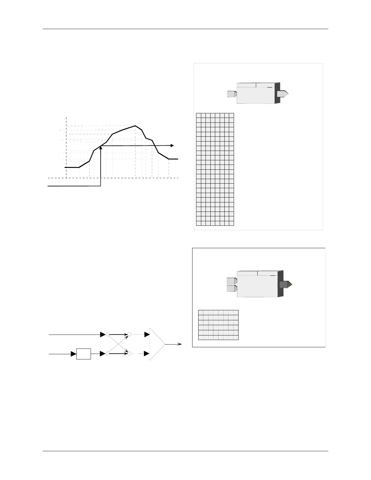
3.2.22 CHR_ - Characterizer
CHR_ function blocks provide 10 segments that can be
used to characterize the X input signal. Individual
segments are configured by entering the Xn, Yn and Xn+1,
Yn+1 points for each segment. All Xn+1 points must be
greater than the associated Xn points. Input X is in
engineering units and the Y points should be in the
engineering units desired for the characterizer output.
BLOCK DIAGRAM
X
OY
Y0
X1
X2 X3
X4
X5
X6
X7
X8
X9
X
10
X
0
Y1
Y10
Y2
Y9
Y3
Y8
Y4
Y7
Y6
Y5
Input Coordinates
Output Coordinates
Input
X
O
utput
Y
CHARACTERIZER
X03131S0
3.2.23 CMP_ - Comparator
CMP_ function blocks compare analog input A with an
external or internal limit setting and provide a high (1)
output when the limit is exceeded.
ACTION - the CMP block can be configured as direct or
reverse action. Direct action will cause the output to go
high when input A is equal to or greater than the limit.
Reverse action will cause the output to go high when
input A is equal to or less than the limit.
BLOCK DIAGRAM
A
O1
O
utput
1
A
nalog
Input
DIR
ect
ACT
ing
LIMIT
+
-
E
xternal
L
imit
EL
X03132S0
DEAD BAND - the output will return from a high (1) output to a low (0) output when input A is less than the limit -
Dead BAND setting for direct action or greater than the limit + Dead BAND for reverse action.
EXTERNAL LIMIT - When input EL is configured, the LIMIT setting will be ignored and the value of input EL
will be used as the limit value.
Input
X
CHARACTERIZER
0
Input Coordinate
X0
(S)
............................ Real
(0.0)
OY
O
utput
Y
CHR_
ESN =
000
X
X
CHARACTERIZER
E
xec.
S
eq.
N
o.
(H)
.......................... 001 to 250
S
E
N
1
Input Coordinate
X1
(S)
............................ Real
(10.0)
X
2
Input Coordinate
X2
(S)
............................ Real
(20.0)
X
3
Input Coordinate
X3
(S)
............................ Real
(30.0)
X
4
Input Coordinate
X4
(S)
............................ Real
(40.0)
X
5
Input Coordinate
X5
(S)
............................ Real
(50.0)
X
6
Input Coordinate
X6
(S)
............................ Real
(60.0)
X
7
Input Coordinate
X7
(S)
............................ Real
(70.0)
X
8
Input Coordinate
X8
(S)
............................ Real
(80.0)
X
9
Input Coordinate
X9
(S)
............................ Real
(90.0)
X
Input Coordinate
X10
(S)
.......................... Real .
(100.0)
X10
0
Output Coordinate
Y0
(S)
......................... Real
(0.0)
Y
1
Output Coordinate
Y1
(S)
......................... Real
(10.0)
Y
2
Output Coordinate
Y2
(S)
......................... Real
(20.0)
Y
3
Output Coordinate
Y3
(S)
......................... Real
(30.0)
Y
4
Output Coordinate
Y4
(S)
......................... Real
(40.0)
Y
5
Output Coordinate
Y5
(S)
......................... Real
(50.0)
Y
6
Output Coordinate
Y6
(S)
......................... Real
(60.0)
Y
7
Output Coordinate
Y7
(S)
......................... Real
(70.0)
Y
8
Output Coordinate
Y8
(S)
......................... Real
(80.0)
Y
9
Output Coordinate
Y9
(S)
......................... Real
(90.0)
Y
0
Output Coordinate
Y10
(S)
....................... Real
(100.0)
Y
1
INPUT X
INPUT X
(H)
..................
l
oop tag.block tag.output (null)
A
nalog Input
COMPARATOR
T
I
D
R
BA
I
Comparator
LIMIT
(S)
..................... Real (0.0)
D
ead
BAND
(S)
.............................. Real (0.5)
DIR
ect
ACT
ing
(S)
.................... NO/YES (YES)
O1
O
utput
1
COMPARATOR
CMP_
ESN = 000
IM
A
EL
E
xternal
L
imit
I
N
P
UT
A
INPUT A
(H)
..........
loop tag.block tag.output (null
)
ESN
E
xec.
S
eq.
N
o.
(H)
................ 001 to 250
N
D
T
C
A
L
E
TU
P
N
I
INPUT EL
(H)
........
loop tag.block tag.output (null)
D
L