UM353-1B Function Blocks
April 2012
3-67
PB3 SWITCH
PB3SW
ESN =
000
PB3 Switch
P
B/
S
witch Output
I
E
S
N
E
xec.
S
eq.
N
o.
(H)
..................... 001 to 250
PS
NC
NC
Input
T
M
MD
HI
ST
atus message
(S)
.. 5 ASCII Char (GREEN)
S
D
H
O
S
TM
D
L
I
ACMD H
OA
C
MD L
NPUT
I
NC
INPUT NO
(H)
...........
loop tag.block tag.output (null)
MD
LO
ST
atus message
(S)
. 5 ASCII Char (RED)
MD
HI
AC
tion message
(S)
... 5 ASCII Char (RED)
MD
LO AC
tion message
(S)
. 5 ASCII Char (GREEN)
NO
MD
M
essage
D
isplay
NO
Input
S
TU
AL
P
O
N
AITC
P
ower
U
p
LAST
(S)
...................... NO/YES (YES)
Switch
ACTION
(S)
................... MOM/SUS (MOM)
NP
U
TI
NO
NPUT
I
MD
INPUT NC
(H)
...........
loop tag.block tag.output
(null)
INPUT MD
(H)
...........
loop tag.block tag.output (null)
3.2.65 PB3SW - PB3 Switch
PB3SW is one of three general purpose switches,
available in each loop. It can be utilized for switching
Boolean signals in such applications as: Start/Stop,
controlling the position of a TSW (Transfer Switch)
function block for switching analog signals, or other
operator initiated actions. PB3SW can only be operated
from the front panel when the A/M function block has
not been configured.
PB3SW can be configured for momentary or sustained
operation. As momentary, the switch will transfer to the
NO position when the button is pressed and it will return
when released. In the sustained mode, the switch will
alternate positions each time the button is pressed. An
unconfigured NC input defaults to 0 and an
unconfigured NO input to 1. The button can be
remotely activated through a command over Modbus or
Modbus/TCP, where explicitly stated in Section 6 Data
Mapping.
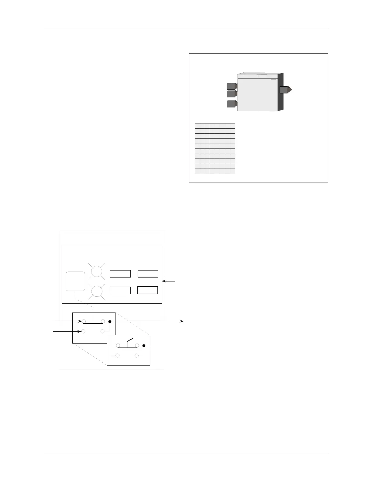
This block operates with an operator faceplate that includes green and red LEDs that are turned on using input MD.
A HI (1) input will turn on the Green LED and a LO the Red LED. The default connection will be the PS output of
the block but should be changed as required to display the correct status. The message parameters do not apply to
the current product.
POWER UP - When the switch is configured for
momentary action, it will always power up in the
NC position. For sustained action, with the
POWER UP parameter set to YES, the switch will
power up in the last position during a hot or warm
start, and during a cold start it will power up in the
NC position. When the POWER UP parameter is
set to NO, the switch will power up in the last
position during a hot start. During a warm or cold
start will power up in the NC position.
R
G
MD
PS
MD Input
P
B
S
witch
Output
Operator Display Interface
UOD MSG
PB3 Switch
MD HI ST
MD HI AC
MD LO ST MD LO AC
PB3
BOD LEDS
Momentary Action
Sustained Action
NO
NC
*****
*****
**********
BLOCK DIAGRAM
BOD - Basic Operator Display
MD - Message Display
UOD - Universal Operator Display
X03128S0

 Loading...