Function Blocks UM353-1B
April 2012
3-58
Operator Display for Pushbuttons
11
Output
11
INPUT 1M
(H)
......................
loop tag.block tag.output
(null)
INPUT 1A
(H) ....................... loop tag.block tag.output
(null)
INPUT 12
(H) ........................
loop tag.block tag.output
(null)
INPUT 11
(H) .......................
loop tag.block tag.output
(null)
INPUT 1F
(H) .......................
loop tag.block tag.output
(null)
11
G
roup
1 TAG
(S) ............................... 6 ASCII Char
(Group1)
Input
11
1
TA
G
I
N
P
UT
I
I
I
I
N
N
N
N
P
P
P
P
U
U
U
U
T
T
T
T
1
2
O
perator
D
isplay
for
P
ushbuttons
LOP#
LOOP #
(S) ................................................ 01 to 25
(null)
O
D
W
I
E
V
VIEW
O
perator
D
isplay
(H) ...................... NO/YES YES
O
ODP_
12Input
12
1A
Input
1A
1MInput
1M
1F
Input
1F
81
Input
81
82
Input
82
8A
Input
8A
8M
Input
8M
8F
Input
8F
Output
12
12
Output
13
13
Output
81
81
Output
82
82
Output
83
83
G
roup
1 P
B
1 TAG
(S) ....................... 6 ASCII Char
(START)
1
2
G
roup
1 S
witch Position
A TAG
(S) .. 6 ASCII Char
(AUTO)
A
TA
G
TA
G
G
roup
1 F
eedback
1 TAG
(S)
........... 6 ASCII Char
(ON)
1
TA
G
TA
G
INPUT 8M
(H)
......................
loop tag.block tag.output
(null)
INPUT 8A
(H) ...................... loop tag.block tag.output
(null)
INPUT 82
(H)
.......................
loop tag.block tag.output
(null)
INPUT 81
(H) ....................... loop tag.block tag.output
(null)
INPUT 8F
(H) .......................
loop tag.block tag.output (null)
I
N
P
UT
I
I
I
I
N
N
N
N
P
P
P
P
U
U
U
U
T
T
T
T
A
M
F
.
Group 8
Group 1
GP
PG
G
roup
1 P
B
2 TAG
(S) ....................... 6 ASCII Char
(STOP
)
S
G
roup
1 S
witch
P
osition
M TAG
(S) .. 6 ASCII Char
(MAN
)
M
S
F
G
roup
1 F
eedback
0 TAG
(S) ........... 6 ASCII Char
(OFF)
0
F
T` A
G
TA
G
TA
G
TA
G
TA
G
G
1
1
G
G
1
1
G
G
1
1
TA
G
TA
G
TA
G
TA
G
8
1
2
A
1
GP
PG
S
M
S
F
0
F
G
8
8
G
G
8
8
G
G
8
8
G
roup
8 TAG
(S) ............................... 6 ASCII Char
(Group8)
G
roup
8 P
B
1 TAG
(S)
....................... 6 ASCII Char
(START)
G
roup
8 S
witch Position
A TAG
(S) .. 6 ASCII Char
(AUTO)
G
roup
8 F
eedback
1 TAG
(S)
........... 6 ASCII Char
(ON
)
G
roup
8 P
B
2 TAG
(S) ....................... 6 ASCII Char
(STOP
)
G
roup
8 S
witch
P
osition
M TAG
(S) .. 6 ASCII Char
(MAN
)
G
roup
8 F
eedback
0 TAG
(S) ........... 6 ASCII Char
(OFF)
1
1
1
1
1
1
2
A
M
F
8
8
8
8
8
2
GP
1
H
I
T
G
roup
1 P
B
1 H
old
I
n
T
ime
(S) ............. 0.1 - 10 sec (1 sec)
1
GP
1
H
I
T
G
roup
1 P
B
2 H
old
I
n
T
ime
(S) ............. 0.1 - 10 sec (1 sec)
G
roup
8
P
B
1 H
old
I
n
T
ime
(S) ............. 0.1 - 10 sec (1 sec)
1
GP
8
H
I
T
G
roup
8
P
B
2 H
old
I
n
T
ime
(S)
............. 0.1 - 10 sec (1 sec)
2
GP
8
H
I
T
Rev. 3
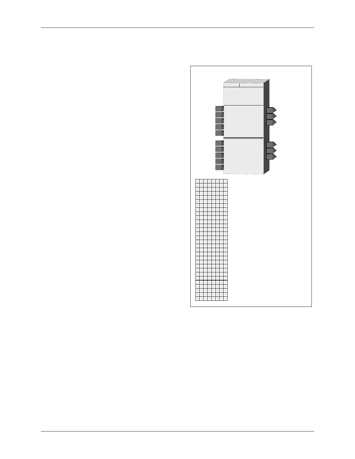
3.2.57 ODP - Operator Display for PushButtons
ODP function blocks are one of five operator displays that
can be used on a one per loop basis to configure local
operator display functions as well as network parameters.
See the i|ware PC faceplate example on the next page.
The ODP function block can provide up to 8 groups of
two pushbuttons and one selector switch. Each group
includes:
• One normally open pushbutton, identified as PB1, on
the local faceplate. It can have a 6-character tag to
identify the button function on a HMI display.
• One normally closed pushbutton, identified as PB2 on
the local faceplate. It can have a 6-character tag for
display on an HMI.
• One two-position selector switch identified as A/M on
the local faceplate. It can have a 6-character tag for
switch position identification on an HMI.
Each group also has a set of 6-character messages
associated with the status of a feedback signal (1/0).
Each pushbutton has a configuration parameter that
controls how long the button function will be held in the
pressed position. The default value is 1 second but can be
set from 0.1 (or scan time if greater than 0.1) to 10
seconds.
The LOOP # parameter is used to index reads and writes
to Modbus parameters. See Section 5 for more
information on network parameters.
The VIEW OD parameter, when set to YES enables the
operator display to be viewed and accessed locally. In
cases where it is desired to view display or operation
parameters only from a network workstation, the
parameter should be set to NO.
During a cold or warm start, the A/M switch will power up in the Auto position. During a hot start, the A/M switch
will power up in the position prior to power down.
Each group can be displayed on the local faceplate using the D button. When first stepping into a loop using the
Loop button, the loop tag will be displayed (e.g. PBDisp1). Pressing the D button will scroll through the groups
displaying the group tag (e.g. MS1036) in the alphanumeric and the value of the feedback in the digital display (e.g.
1). The feedback message associated with this feedback value can be viewed on the local faceplate using the
UNITS button. The A/M button will display the position of the group selector switch and enable switching the
group selector switch between auto and manual.

 Loading...