EasyManua.ls Logo

Siemens 353 User Manual

Siemens 353
246 pages
To Next Page IconTo Next Page
To Previous Page IconTo Previous Page
Page #74 background imageLoading...
Page #74 background image
Function Blocks UM353-1B
April 2012
3-44
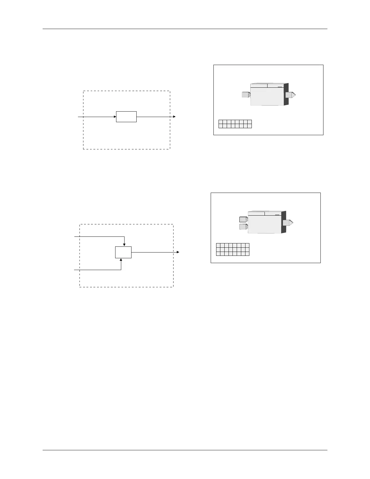
3.2.39 EXP_ - NATURAL EXPONENTIATION
EXP_ function blocks perform the natural exponentiation function,
base “e”. The output will be the value “e” raised to the power of
input X.
3.2.40 EXT_ - EXPONENTIATION
EXT_ function blocks will provide an output that equals the Y
input raised to the power of X input. All negative values of input
Y will be treated as 0.0. When input Y is 0.0 and X is negative,
the output will be set to the maximum number (i.e. 1.17...e38).
Input
X
NATURAL EXPONENTIATION
O1
O
utput
1
O
1
= e
EXP
ESN =
000
X
E
E
xec.
S
eq.
N
o. ..................... 000 to 250 (000)
X
T
U
P
N
I
INPUT X
..............
loop tag.block tag.output (null)
SN
X
BLOCK DIAGRAM
O1X
Input
X
O
utput
1
.
.
e
X
Input
X
EXPONENTIATION
O1
O
utput
1
O
1
= Y
EXT
ESN =
000
X
E
E
xec.
S
eq.
N
o. ..................... 000 to 250 (000)
Y
T
U
P
N
I
INPUT Y
..............
loop tag.block tag.output (null)
Input
Y
Y
X
T
U
P
N
I
SN
INPUT X
..............
loop tag.block tag.output (null)
X
BLOCK DIAGRAM
O1
X
Y
Input X
Input Y
O
utput
1
.
.
Y
X

Table of Contents

Question and Answer IconNeed help?

Do you have a question about the Siemens 353 and is the answer not in the manual?

Siemens 353 Specifications

General IconGeneral
CPUCPU 353
Inputs16 digital inputs, 24 V DC
Outputs16 digital outputs, 24 V DC, 0.5 A
CommunicationMPI
Power Supply24 V DC

Summary

PREFACE

General Warnings and Cautions

Highlights hazards like high voltages and the need for qualified personnel and safety adherence.

1.0 INTRODUCTION

1.2 FUNCTION BLOCKS

Explains the controller's software architecture based on reusable function blocks and their types.

2.0 CONFIGURATION OVERVIEW

2.5 CONFIGURATION PROCEDURE

Outlines the steps for configuring the controller, both locally via faceplate and remotely via PC.

3.0 FUNCTION BLOCKS

3.2 I/O AND LOOP FUNCTION BLOCKS

Describes input/output and loop function blocks, listed alphabetically.

4.0 FACTORY CONFIGURED OPTIONS

4.1 FCO101 - Single Loop Controller w/ Tracking Setpoint

Describes FCO101, a single loop controller configured in Loop01, providing setpoint tracking.

6.0 DATA MAPPING

7.0 INSTALLATION

7.4 ELECTRICAL INSTALLATION

Contains details for wiring the Siemens 353, including general wiring guidelines and specific I/O wiring.

8.0 LOCAL FACEPLATE OPERATION

8.3 AUTOTUNE PROCEDURE

Outlines the procedure for initiating and performing the autotune function for controller tuning via the TUNE pushbutton.

9.0 CONTROLLER AND SYSTEM TEST

9.1 CONTROLLER CONFIGURATION AND TEST

Provides steps to configure and test the controller, including connections, power, and initial setup.

10.0 MAINTENANCE

10.3 TROUBLESHOOTING

Guides users on troubleshooting controller issues using error codes, power-up sequences, and assembly substitution.

10.4 ERROR CODES

Describes off-line and on-line error codes, status codes, and their corresponding corrective actions.

10.5 ASSEMBLY REPLACEMENT

Outlines procedures for replacing controller assemblies, including MPU Controller Board, I/O Expander Board, and Display Assembly.

11.0 CALIBRATION

13.0 MODEL DESIGNATION AND SPECIFICATIONS

Related product manuals