The FLoW scale is the standardization from 0% to 100% in the
range between the 'YA' and 'YE' parameters. Over this range, the
setpoint w is also always 0% to 100%. This results in a more or less
flow-proportional display and position feedback. The flow-propor‐
tional display and position feedback also results from the use of
process valve characteristics.
In order to calculate the control deviation, the setpoint in the display
is also shown in the corresponding scale.
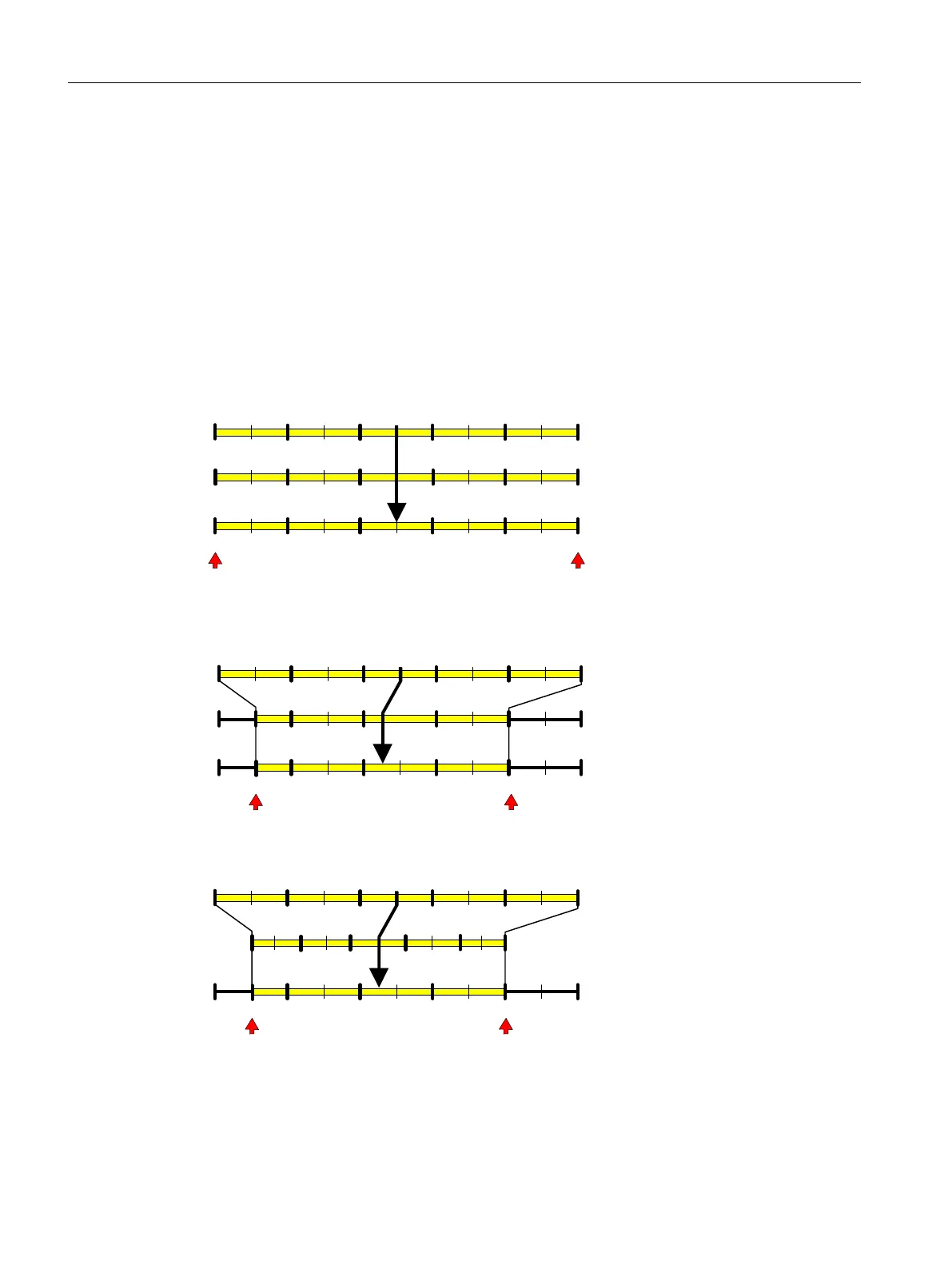
Below, the example of an 80-mm linear actuator is used to illustrate
the dependence of the stroke on the scaling as well as on the 'YA'
and 'YE' scaling parameters; see the following figure.
Factory setting: MPOS
7UDYHOOLPLWORZ7UDYHOOLPLWKLJK
0HFKDQVWURNH
DFWXDOYDOXH
PP
PPPPPPPPPP
6HWSRLQW
0HDVXULQJYDOXHGLVSOD\
6HWSRLQWGLVSOD\
Figure 8-3 YNRM = MPOS or YNRM = FLoW; default: YA = 0 % and YE = 100 %
7UDYHOOLPLWORZ7UDYHOOLPLWKLJK
0HFKDQVWURNH
DFWXDOYDOXH
PP
PPPPPPPPPP
6HWSRLQW
0HDVXULQJYDOXHGLVSOD\
6HWSRLQWGLVSOD\
Figure 8-4 Example: YNRM = MPOS with YA = 10 % and YE = 80 %
7UDYHOOLPLWORZ7UDYHOOLPLWKLJK
0HFKDQ6WURNH
DFWXDOYDOXH
PP
PPPPPPPPPP
6HWSRLQW
0HDVXULQJYDOXHGLVSOD\
6HWSRLQWGLVSOD\
Figure 8-5 Example: YNRM = FLoW with YA = 10 % and YE = 80 %
Parameter assignment
8.4 Description of parameters
SIPART PS2 with 4 to 20 mA/HART
152 Operating Instructions, 11/2019, A5E00074631-AE

 Loading...


