4.5.4 Inductive Limit Switches (ILS) 6DR4004 6G / -8G
4.5.4.1 Inductive Limit Switches (ILS) - Mode of operation and equipment features
Function
If the basic unit requires electrically independent limit messages, the Inductive Limit Switches
(ILS) with slotted initiators is used instead of the Digital I/O Module (DIO).
● A digital output is used to display a group fault message. Compare with the function of the
Digital I/O Module (DIO). The floating digital output is implemented as an automatic fault
indicating semiconductor output.
● The other two digital outputs are used to signal the two limits L1 and L2 which can be
adjusted mechanically using slotted initiators. These two digital outputs are electrically
independent from the remaining electronic unit.
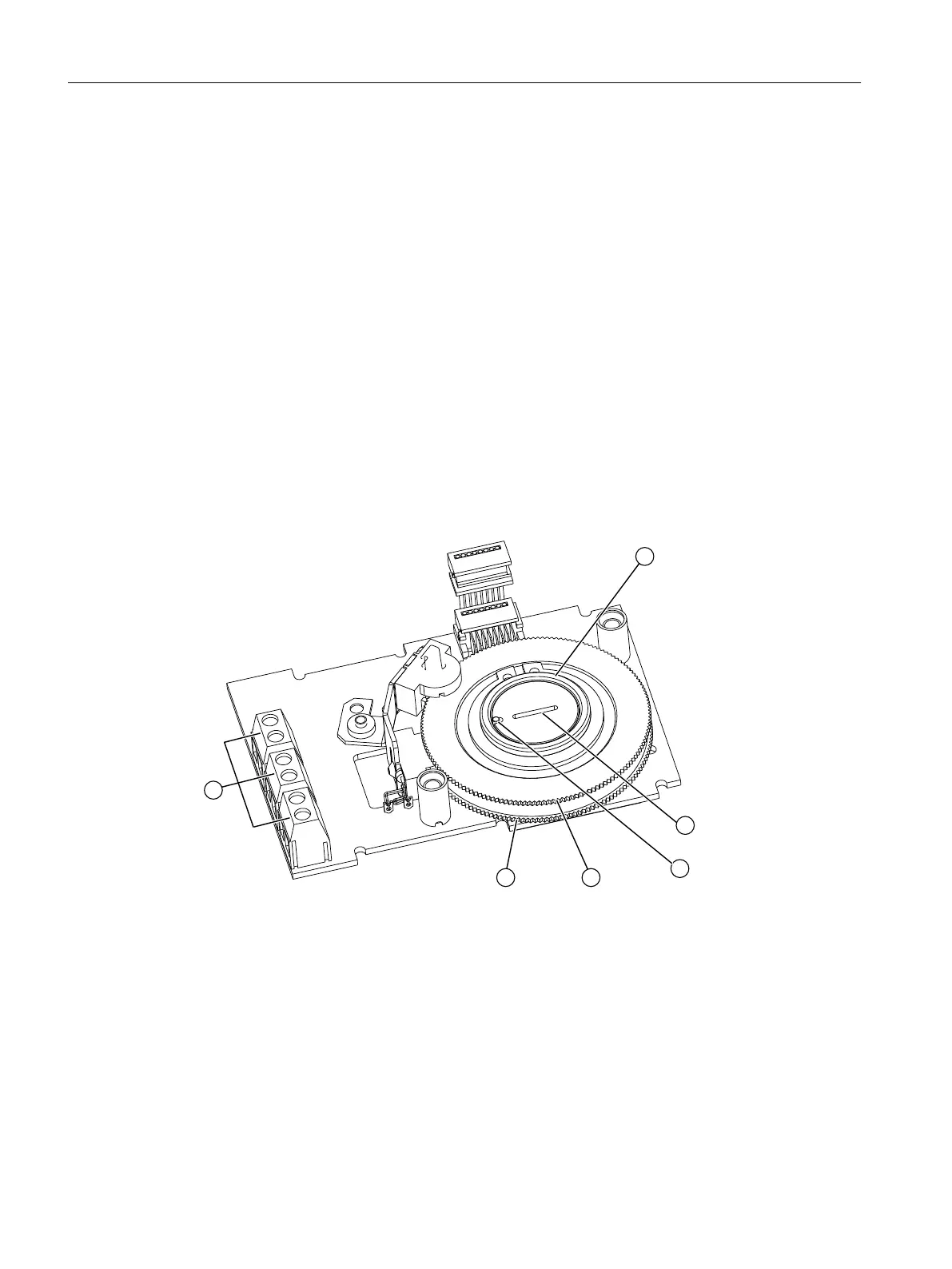
Device features
① Actuating disk bearings ② Special screw
③ Pin ④ Upper actuating disk for limit L1, terminals 41/42
⑤ Lower actuating disk for limit L2, termi‐
nals 51/52
⑥ Digital outputs
Figure 4-17 Inductive Limit Switches (ILS), schematic representation
The Inductive Limit Switches (ILS) have three digital outputs ⑥.
Installing/mounting
4.5 Installing option modules
SIPART PS2 with 4 to 20 mA/HART
62 Operating Instructions, 11/2019, A5E00074631-AE

 Loading...


