4.5.6 Internal NCS module (iNCS) 6DR4004-5L / -5LE
Function
Wear-free, non-contacting position detection
Device features
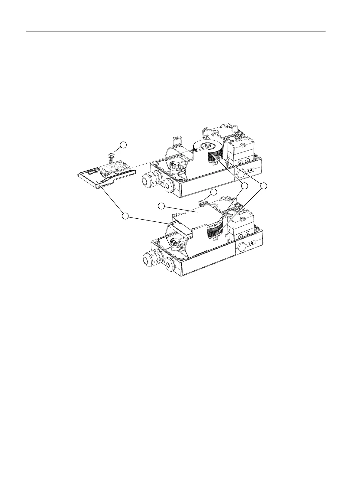
① Internal NCS module 6DR4004-5L. ④ Adjustment wheel for the magnet clamp
② Insulating cover, yellow ⑤ Adjustment wheel for the friction clutch (without
function)
③ Ribbon cable of the internal NCS mod‐
ule
Figure 4-19 Installing the internal NCS module, schematic diagram
Requirement
● The slot required for the internal NCS (iNCS) module in the rack is free. The following option
modules use the same slot in the rack:
– Digital I/O Module (DIO)
– Inductive Limit Switches (ILS)
– Mechanic Limit Switches (MLS)
– Internal NCS module
● The positioner is mounted, or is to be mounted, directly on the valve using the positioner
shaft.
Installing/mounting
4.5 Installing option modules
SIPART PS2 with 4 to 20 mA/HART
68 Operating Instructions, 11/2019, A5E00074631-AE

 Loading...


