5.2.3.5 Analog Input Module (AIM) 6DR4004-6F / -8F
Procedure
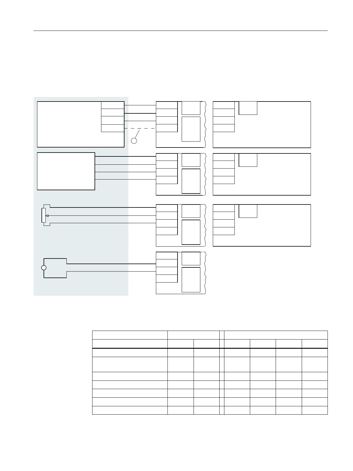
1. Connect the external position detection as follows.
;
;
;
;
21
;
1
3RVLWLRQ7UDQVPLWWHUV
JUHHQ
EODFN
EURZQ
\HOORZ
1&66HQVRU
6LJQDOP$RU9
3RWHQWLRPHWHUN˖N˖N˖
'5(6
'5(6
'5(6
'5(6
5HI
3RV
*1'
9FF
5HI
3RV
*1'
9FF
'5)Q([
6
6
21
6
6
6
6
5HI
3RV
*1'
9FF
'5)([
6
6
21
$QDORJ,QSXW0RGXOH
$,0
$QDORJ,QSXW0RGXOH
$,0
6
6
21
5HI
3RV
*1'
9FF
21
21
21
21
6
6
6
6
6
6
5HI
3RV
*1'
9FF
;
;
$QDORJ,QSXW0RGXOH
$,0
6
6
21
5HI
3RV
*1'
9FF
21
21
6
6
6
6
6
6
5HI
3RV
*1'
9FF
6
6
6
6
6
6
5HI
3RV
*1'
9FF
1&6'511
① Connection of terminal Vcc is only needed for 6DR4004-2ES, -3ES and -4ES.
2. If potentiometers or external signal sources are used, configure the switch blocks in
accordance with the following table:
Measuring range Switch block 1 Switch block 2
S1-1 S1-2 S2-1 S2-2 S2-3 S2-4
6DR4004-.N/P/R (NCS) ON OFF ON OFF OFF OFF
6DR4004-1ES/-2ES/-3ES/-4E
S
ON OFF ON OFF OFF OFF
10 ... 20 kΩ ON OFF ON OFF OFF OFF
5 kΩ OFF ON ON OFF OFF OFF
3 kΩ OFF OFF ON OFF OFF OFF
20 mA OFF OFF ON OFF ON OFF
10 V OFF OFF OFF ON OFF OFF
Connection
5.2 Electrical wiring
SIPART PS2 with 4 to 20 mA/HART
Operating Instructions, 11/2019, A5E00074631-AE 87

 Loading...


