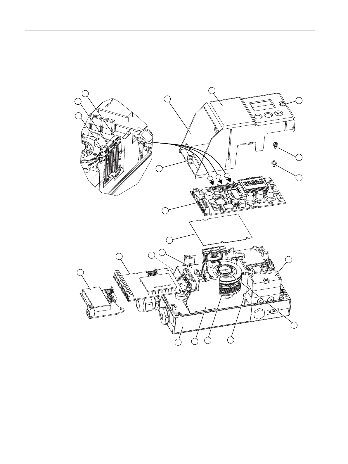
4.5.1.1 Opening the standard and intrinsically safe version
Overview screen
① Module cover ⑪ Adapter
② Fixing screws module cover ⑫ Transmission ratio selector
③ Fixing screws basic electronics ⑬ Pneumatic block
④ Ribbon cable/connector for fitted potentiom‐
eter or fitted Analog Input Module (AIM)
⑭ Warning label on the side opposite the
nameplate
⑤ Ribbon cable/connector for Digital I/O Mod‐
ule (DIO), Inductive Limit Switches (ILS) or
Mechanic Limit Switches (MLS)
⑮ Inductive Limit Switches (ILS) or Mechanic
Limit Switches (MLS)
Installing/mounting
4.5 Installing option modules
SIPART PS2 with 4 to 20 mA/HART
52 Operating Instructions, 11/2019, A5E00074631-AE

 Loading...


