B.2.2.1 Mounting on part-turn actuator
Requirement
1. An Analog Input Module (AIM) built into the positioner
2. A non-contacting sensor for part-turn actuators 6DR4004-.N.10 or 6DR4004-.N.40
3. A part-turn actuator with interface acc. to VDI/VDE 3845 and mounting console acc. to VDI/
VDE 3845, or
A part-turn actuator with manufacturer-specific interface
NOTICE
Incorrect mounting
A clearance of 3 mm must be maintained between the magnet and the mounting console in
order to ensure correct measurement of the actuator position. The values transferred may be
incorrect if this clearance is not given.
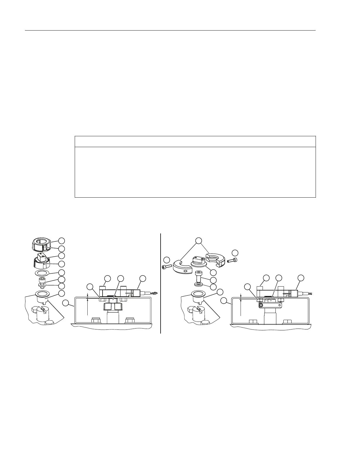
● Maintain a clearance of 3 mm between the top edge of the magnet ④ and the top edge of
the mounting console ⑩.
Description
s
s
① Tensioning ring ⑧ Washer
② Hex socket head screw size M3x12 ⑨ Clamping table
③ Spring element ⑩ Mounting console
④ Magnet ⑪ Hexagon nut
⑤ Hooks ⑫ Hex socket head screw size M6x25
⑥ Plastic washer ⑬ Non Contacting Sensor (NCS)
⑦ Hex socket head screw size M6x12
Figure B-4 Mounting on part-turn actuator with magnet holder made of glass fiber reinforced polyester (left figure) or
anodized aluminum (right figure)
External position detection
B.2 Non-Contacting Sensor
SIPART PS2 with 4 to 20 mA/HART
274 Operating Instructions, 11/2019, A5E00074631-AE

 Loading...


