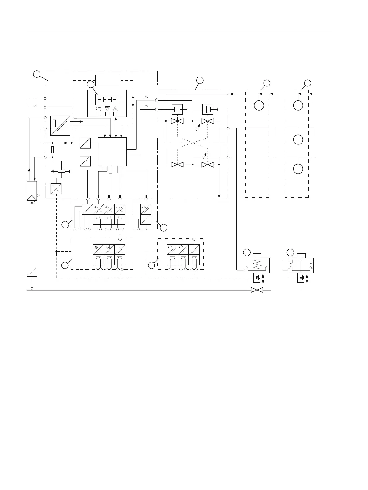
3.4.1 Block circuit diagram for single-acting or double-acting actuators
6WURNH
:
:
$
'
$
'
S
',
,
:
,
:
\
[
[
8
\
\
',$$
$$
$$
8
8
,
S
S
6WURNH
6XSSO\
DLU
3=
<
<
<<
<<
<
3=
<
([KDXVW
DLU
0LFUR
FRQWUROOHU
6XSSO\
DLU
6XSSO\
DLU
+$57
9
9
① Basic electronics with microcontroller and input circuit
② Control pad with display and buttons
③ Single-acting or double-acting pneumatic block
④ Analog Output Module (AOM) for positioners
⑤ Digital I/O Module (DIO) for 3 digital outputs and 1 digital input
⑥ Inductive Limit Switches (ILS)
⑦ Mechanic Limit Switches (MLS)
⑧ Spring-loaded pneumatic actuator (single-acting)
⑨ Pneumatic actuator (double-acting)
⑩ Pressure sensor module
⑪ Pressure gauge block
Figure 3-10 Block circuit diagram for the electropneumatic positioner, functional diagram
Description
3.4 Mode of operation
SIPART PS2 with 4 to 20 mA/HART
32 Operating Instructions, 11/2019, A5E00074631-AE

 Loading...


