5.2.2 Connection diagram split range
8
,
9
P$
8
,
$
(
$
(
8
([
,
([
([G([WQ([
([L([HF
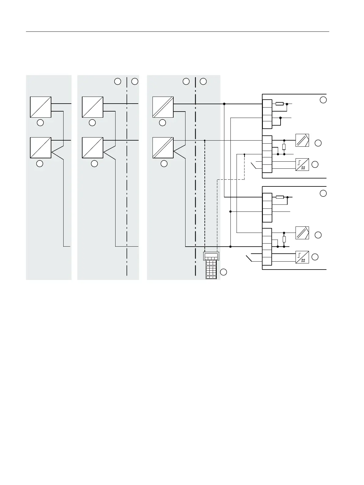
① Non-hazardous area ③ Device 1 ⑥ Device 2
② Hazardous area ④ Travel range ⑦ Travel range
⑨ Signal source ⑤ Digital input DI1 ⑧ Digital input DI1
⑩ Power source
⑪ HART communicator
nEx = Non-explosion-proof device version
Figure 5-6 Series connection of 2 positioners, e.g. split range
Connection
5.2 Electrical wiring
SIPART PS2 with 4 to 20 mA/HART
82 Operating Instructions, 11/2019, A5E00074631-AE

 Loading...


