Figure 9-3 PFD distribution
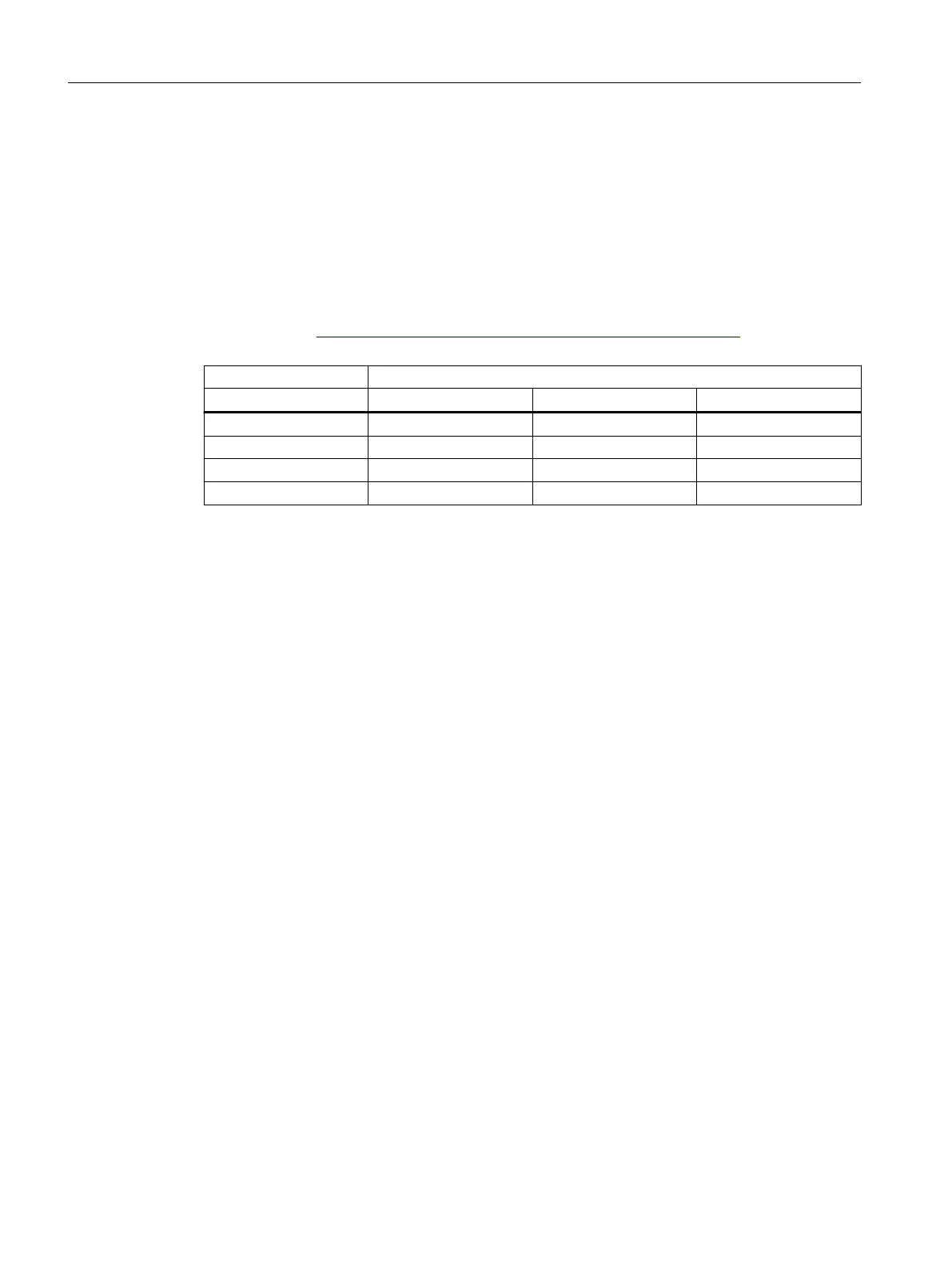
The following table shows the achievable Safety Integrity Level (SIL) for the entire safety-
related system for type A devices depending on the safe failure fraction (SFF) and the hardware
fault tolerance (HFT).
● Type A devices include analog transmitters and solenoid valves without complex
components, e.g. microprocessors (see also IEC 61508, Section 2).
● The specific values for your device are listed in the manufacturer's declaration of the device
(SIL Declaration of Conformity, Functional Safety according to IEC 61508 and IEC 61511):
Certificates (http://www.siemens.com/processinstrumentation/certificates).
SFF HFT for type A devices
0 1 2
< 60% SIL 1 SIL 2 SIL 3
60 to 90% SIL 2 SIL 3 SIL 4
90 to 99% SIL 3 SIL 4 SIL 4
> 99% SIL 3 SIL 4 SIL 4
9.4 Settings
No special parameter settings are required for the safety function.
Protection against configuration changes
You should attach the housing cover so that the device is protected against unwanted and
unauthorized changes/operation.
Checking the safety function
Prerequisite for checking the safety function
● Positioner is in operation.
● The actuator belonging to the positioner is not in the safety position.
Procedure
1. On the positioner, switch the signal source to 0 mA or the power supply source to 0 V.
2. Reduce the inlet pressure (PZ) to a third of the maximum supply pressure.
3. Always carry out the validation of the safety function with positioner, actuator and process
valve under operating conditions.
Result
The actuator brings the process valve to the specified safety position.
Functional safety
9.4 Settings
SIPART PS2 with 4 to 20 mA/HART
194 Operating Instructions, 11/2019, A5E00074631-AE

 Loading...


