6DR5..0 6DR5..1 6DR5..2 6DR5..3
G¼ 1/4-18 NPT G¼ 1/4-18 NPT
M - 26.5 [1.04] 41.5 [1.53] 40 [1.57]
N - 7.5 7.5 7.5
O 14.5 [0.57] 14.5 [0.57] 14.5 [0.57] 15.5 [0.61]
P > 150 (5.91)
Adhere to this minimum clearance P for service and maintenance above the cover.
Dimensions in mm [inch]
*) Dimensions only apply to double-acting actuators.
6DR5..0 Polycarbonate enclosure; dimensions with pneumatic connection G¼ or 1/4-18 NPT
6DR5..1 Aluminum enclosure, single-acting
6DR5..2 Stainless steel enclosure, without inspection window
6DR5..3 Aluminum enclosure, single/double-acting; dimensions with pneumatic connection
G¼ or 1/4-18 NPT
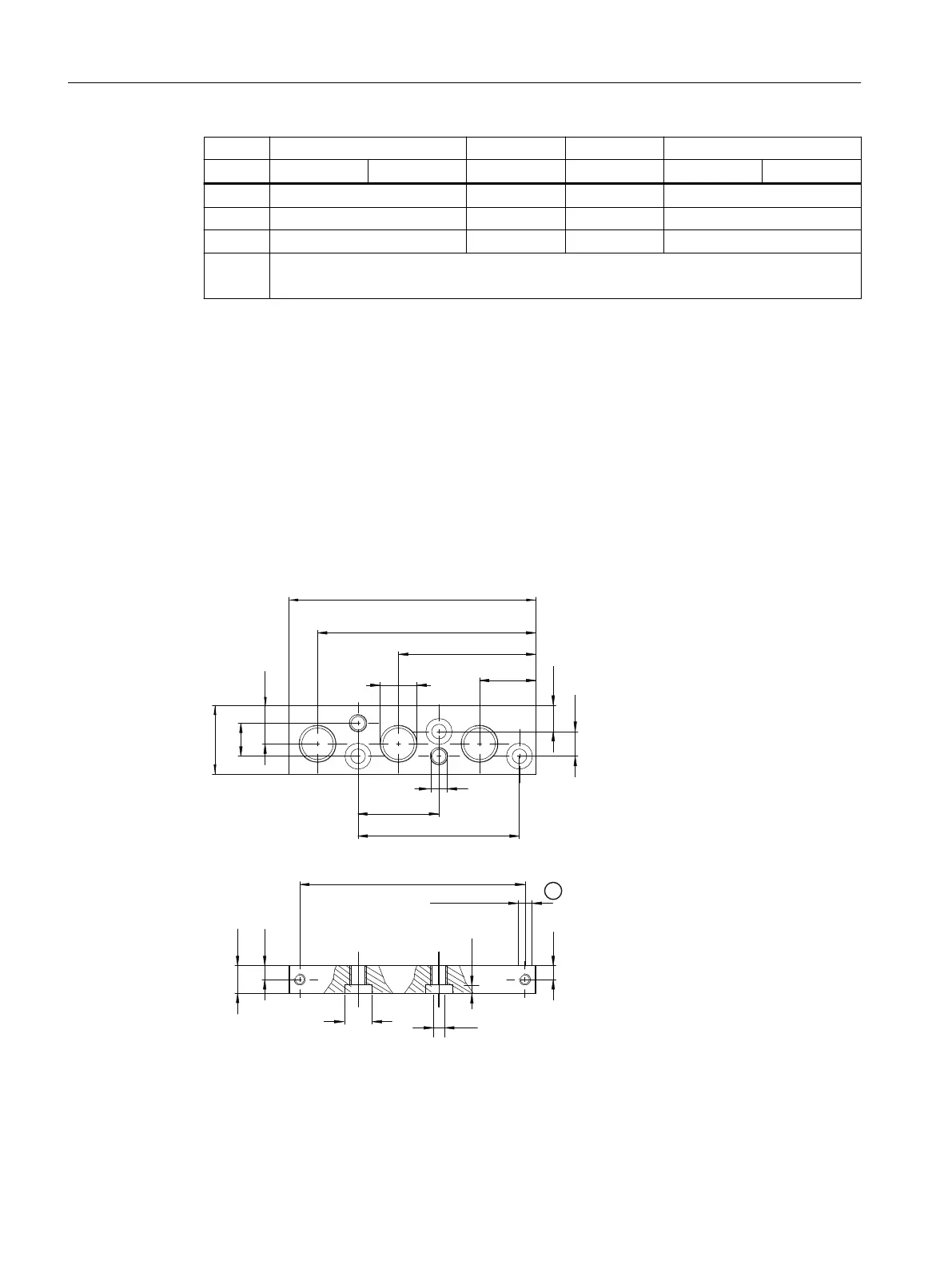
13.2 Terminal strip for enclosures 6DR5..0 and 6DR5..3
[
*RU
ಯ137
[0
0
*
137
① Thread depth
Figure 13-2 Terminal strip, dimensions in mm (inch)
Dimension drawings
13.2 Terminal strip for enclosures 6DR5..0 and 6DR5..3
SIPART PS2 with 4 to 20 mA/HART
258 Operating Instructions, 11/2019, A5E00074631-AE

 Loading...


