Interface Modules SWT 3000 Equipment Manual
Page - 8 Edition p3_3_2x 08/09 © SIEMENS AG 2008
Signal acquisition through the binary inputs
If a message is detected by the binary inputs (BE1...BE4) of the module (edge change) an inter-
rupt request is sent to the PU3. The IFC module is connected to the PU3 by a ribbon cable via con-
nector X3 at the front. If an interrupt is detected by the PU3 the status of the binary inputs can be
read by the PU3 via lines DIF0...DIF3.
In order to suppress interference pulses a signal must be applied to the binary input for at least
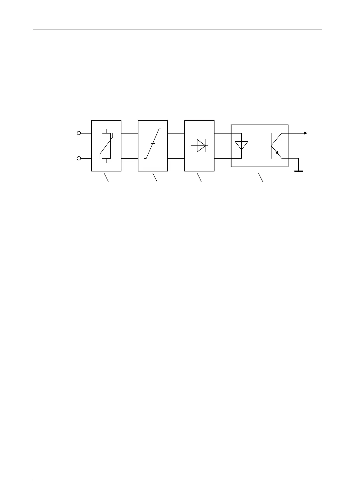
1 ms before the interrupt request is sent. The following figure shows the block diagram of a binary
input.
123 4
Figure 8: Binary inputs of modules IFC-D and IFC-P
Each of the binary inputs contains the following components:
1 Protective circuit
2 Setting of the input rated voltage
3 Rectifier
4 Optocoupler
1: The required security against destruction and interference is provided by the protec-
tive circuit.
2: The input rated voltage can be set to the values 24V, 48/60V, 110V and 250 V DC
with the links X43...X58. The operating point is at 80% of the selected voltage (the
link settings can be found in Chapter 2).
3: Rectification ensures that the input signal is polarity-neutral.
4: The optocoupler isolates the input circuit electrically from the electronic system

 Loading...


