SWT 3000 Equipment Manual Installation and Commissioning
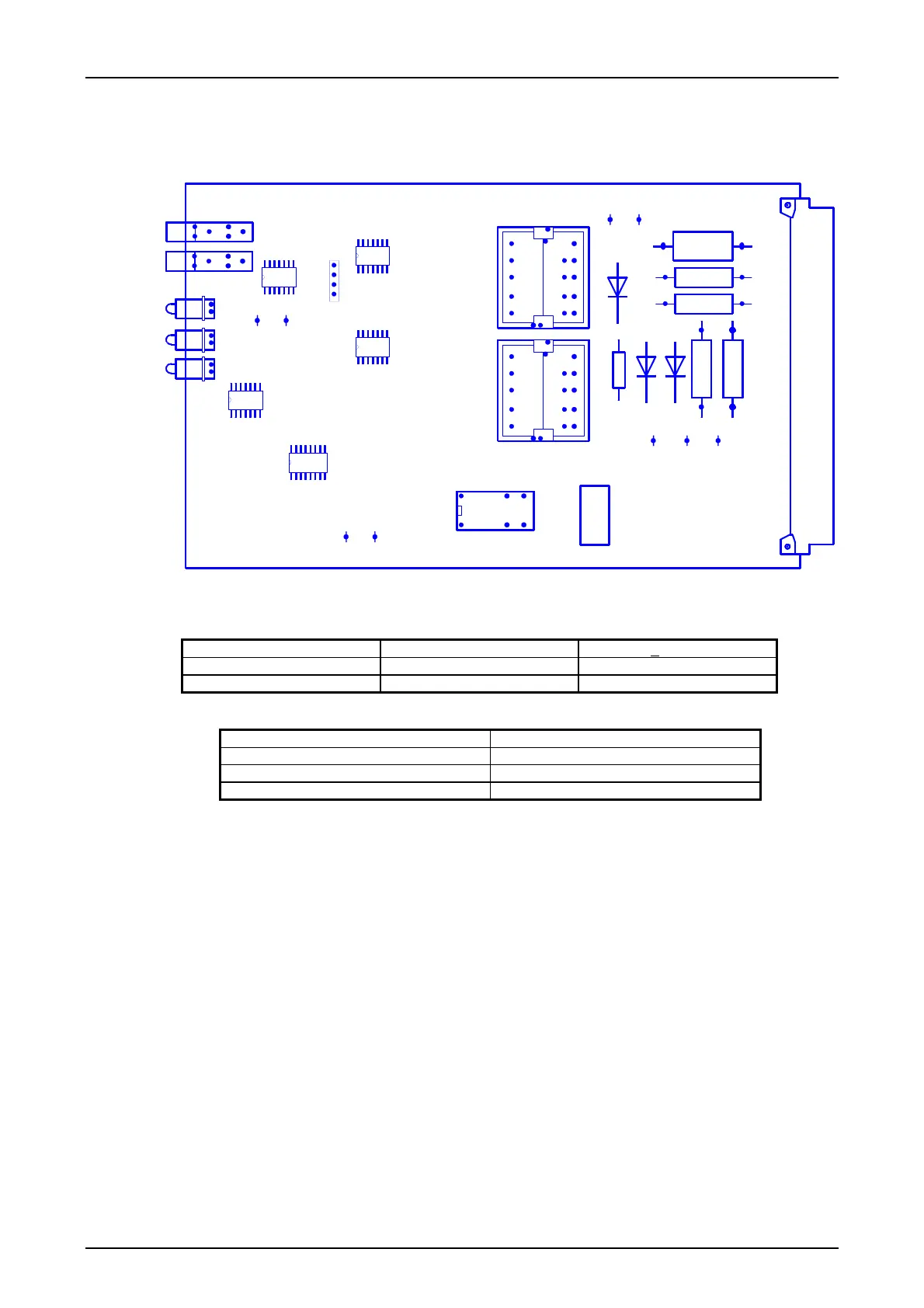
Jumper settings for the CLE module
T1
1
6
T2
1
6
K1
X5 X4 X3
1
2
X10
1
2
X9
H3
H2
H1
N5
D1
N4
N2
N3
X2
R9
R8
R
1
3
6
R
1
2
5
R
1
2
4
C
1
0
0
W3
W2
W1
W6 W5
X12 X11
W4
V
1
0
3
V
1
0
2
R7
V
5
X13 X14
W7
X15 X16
W8
Figure 11: Position of the jumpers on the CLE module
Table 24:
Jumper setting for the input and output impedance
Setting 600 Ohm >
5kOhm
Input impedance W4 without W4
Output impedance W5 W6, W7, W8
Table 25: Jumper setting for the receive signal gain
Receive signal gain [dB] Jumper X2 in pos.
0 W1
6 W2
12 W3
© SIEMENS AG 2008 Edition p3_3_2x 08/09 Page - 23

 Loading...


