SWT 3000 Equipment Manual ALRS and ALR Module
© SIEMENS AG 2008 Edition p3_3_2x 08/09 Page - 7
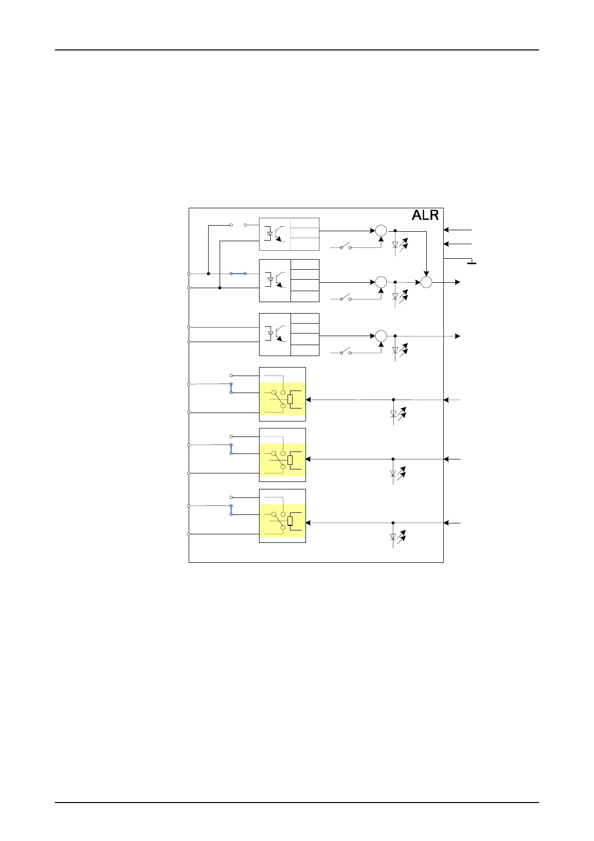
The ALR module
The ALR module provides as well 3 alarm relays like the ALRS module. The difference to the
ALRS module is in the two binary inputs. The input voltage is adjustable to 24V, 48/60V, 110V
resp. 250V DC. The binary input 1 is used for the clock synchronization of the iSWT. Either an ex-
ternal synch. pulse is connected or the input is alternatively configurable as an input for entering
IRIG-B signals. Additionally the ALR module provides a LED for visual indication of the state for
each binary input and for each alarm output. The LED are visible after removal of the front panel.
For more details refer to chapter 4 commissioning.
Block diagram
ALR_INFO.vsd/Sheet-1
2008-03-14/DOE
250V
110V
48/60V
24V
24V
12V
5V
X14 X15
X16 X17
BI1
BI1_A
BI1_B
250V
110V
48/60V
24V
BI2_A
BI2_B
BI2
ALA1_A
ALA1_B
A21
C23
X7
X6
X5
K1
ALA2_A
ALA2_B
A28
A25
X10
X9
X8
K2
ALA3_A
ALA3_B
A32
C30
X13
X12
X11
K3
A1
C3
A5
A8
ALA1
ALA2
ALA3
BI1-Test (S1/2)
IRIG-B-Test (S1/4)
BI2-Test (S1/1)
H5
H6
H4
BI1_IN_L
BI2_IN_L
ALA1_OUT_L
H3
ALA2_OUT_L
H2
ALA3_OUT_L
H1
IRIG-B
+5V
+12V
u s e r i n t e r f a c e s
s y s t e m i n t e r f a c e s
(„USYNC“)
(„EALR“)
(„SALR/NDALR“)
(„GENALR“)
Figure 4: ALR Block diagram

 Loading...


