Installation and Commissioning SWT 3000 Equipment Manual
Operation with the PLC system PowerLink
When using the SWT 3000 with the PowerLink PLC system the following settings must be made
depending on the configuration:
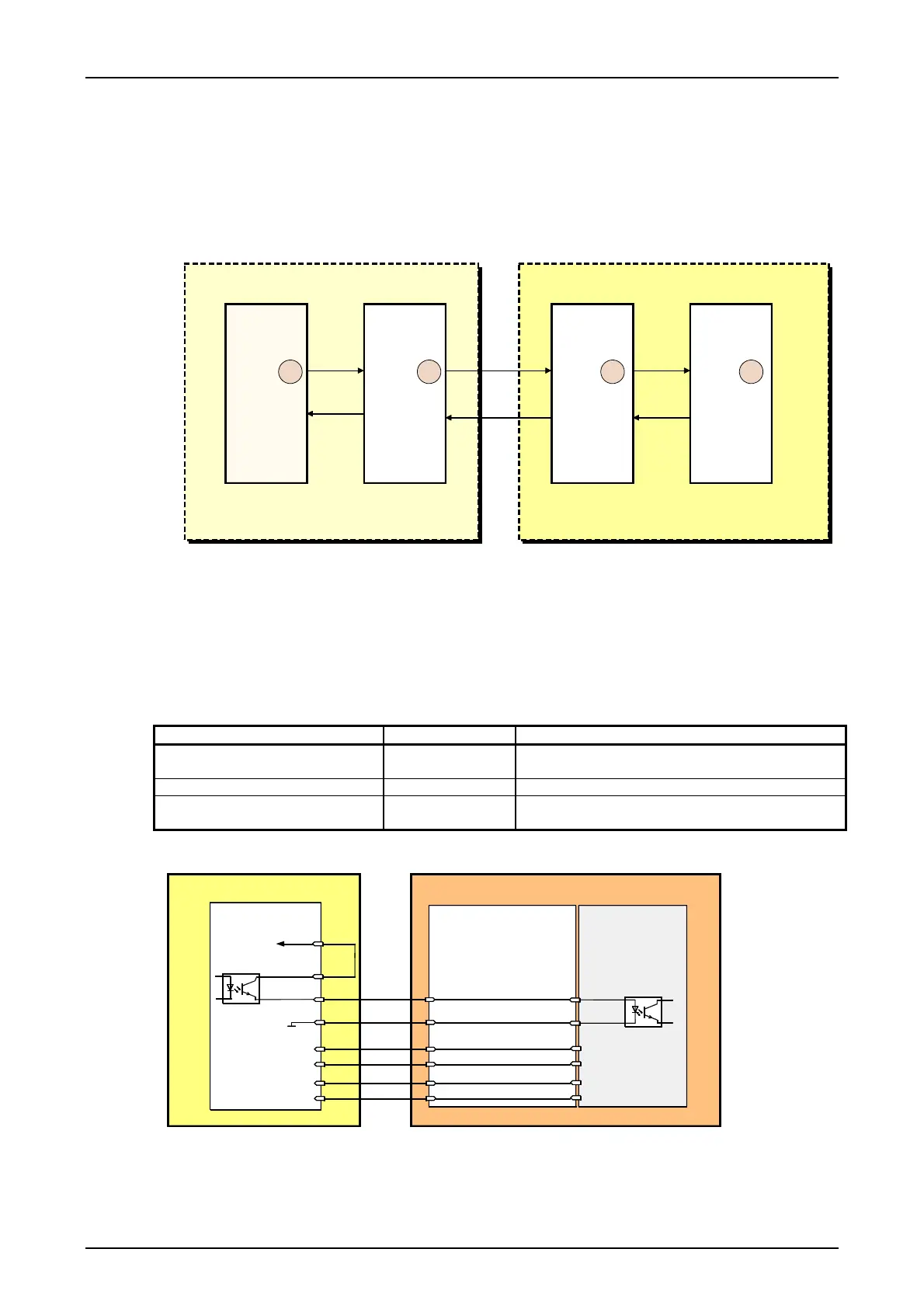
Connection via a VFx module :
PU3 CLE
VFx
CSP
1 2 3 4
SWT 3000 PowerLink
Figure 19: Setting options for the protection transmit level for connection via VFx module
The output level of the PU3f (1) is set with the service PC and amplified by +11 dB on the CLE
module (2).
A level of -10 dB is required at the input of the VFx module (3). The levels in the PowerLink are
set automatically from the system depending on the device configuration. They are displayed in the
menu <Information / Service> and can be measured at the CSP resp. PLE output.
Table 40: SWT 3000 transmit level
Measuring point Level [dB] Comment
PU3f module output -21 Setting with control PC on the SWT 3000 PU3f-
module (1)
VFx input -10
CSP module output (4)
dep. on device
configuration
Automatic Tx level adjustment from the system
* In case of coded tripping (CT) the level has to be adjusted 6dB less. This is causing also 6dB less level at the output of
the CLE
CLE
CFS
P12V
S6IN_A
S6AB
GND12
S6IN_B
S6AB_GND
F6AB_A
F6AN_B
F6AN_A
F6AB_B
a18
c13
c11
a20
c5
c3
c9
c7
4wire input A
3
4
2
1
6
5
wh/gn
bu
or
wh/or
wh/bu
X1
VFx
SWT 3000
PowerLink
4wire input B
4wire output A
4wire output B
gn
RJ45
Connector panel
Port 3 resp. 4
Figure 20: Connecting cable between the SWT 3000 and the VFx module
Page - 34 Edition p3_3_2x 08/09 © SIEMENS AG 2008

 Loading...


