SWT 3000 Equipment Manual Functional Description
© SIEMENS AG 2008 Edition p3_3_2x 08/09 Page - 25
Mode 5D (only for digital line interfaces LID)
Operating mode 5D is designed exclusively for the digital lines interfaces LID-1 and/or LID-2. In
this mode 1...8 signal inputs and 1...8 signal outputs are available with
two IFC modules. The sta-
tes of the signal inputs are transmitted to the distant station transparently and can be jumpered to
signal outputs there.
This operating mode was used in system SWT 2000 D.
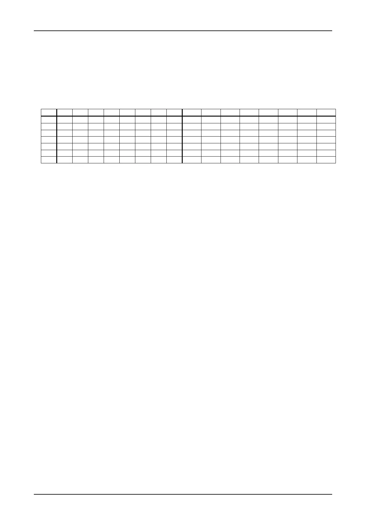
Table 13: Possible output jumper settings in mode 5D
idx BI1 BI2 BI3 BI4 BI5 BI6 BI7 BI8 CO1 CO2 CO3 CO4 CO5 CO6 CO7 CO8
1 0 0 0 0 0 0 0 0 X/1 X/1 X/1 X/1 X/1 X/1 X/1 X/1
2 1 0 0 0 0 0 0 0 X/1 X/1 X/1 X/1 X/1 X/1 X/1 X/1
3 0 1 0 0 0 0 0 0 X/1 X/1 X/1 X/1 X/1 X/1 X/1 X/1
4 1 1 0 0 0 0 0 0 X/1 X/1 X/1 X/1 X/1 X/1 X/1 X/1
: : : : : : : : : : : : : : : : :
255 0 1 1 1 1 1 1 1 X/1 X/1 X/1 X/1 X/1 X/1 X/1 X/1
256 1 1 1 1 1 1 1 1 X/1 X/1 X/1 X/1 X/1 X/1 X/1 X/1
Note: the states of the SYNC signals from LID-1 OR LID-2 can be programmed on CO1...8.
SYSWIN can administer up to 20 jumper settings
Possible settings:
X = no reaction: The state of the signal output is not affected.
1 = switch on: The signal output is switched on or “retriggered“.
The default program setting is 1:1 (“transparent“); i.e.: BI1=CO1, BI2=CO2, ... , BI8=CO8

 Loading...


